中文简体
中文简体 English
 Español
Content
What Are 75 Ohm Braiding Cables
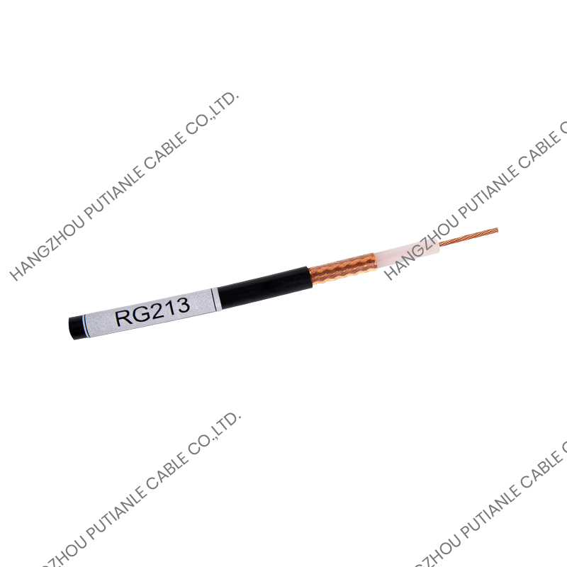
75 ohm braiding cables refer to coaxial cables engineered with a characteristic impedance of 75 ohms, paired with a braided outer conductor that shields the internal signal-carrying core from electromagnetic interference. The term "braiding" describes the woven metallic mesh, typically made of copper or copper-plated steel, that surrounds the cable's dielectric insulation and inner conductor. This braid serves as both a shield and, in many designs, part of the return path for the electrical signal, making its quality directly responsible for the cable's overall performance.
The 75 ohm impedance standard is specifically chosen for applications involving video, radio frequency, and broadcast signal transmission, as opposed to the 50 ohm standard commonly used in data and two-way radio communication. This distinction matters because impedance mismatches between cables and connected equipment can cause signal reflection, resulting in degraded picture quality, signal loss, or interference in the transmitted data.
Understanding the Structure of 75 Ohm Braiding Cables
A typical 75 ohm braiding cable is built from four primary layers, each serving a specific function in maintaining signal integrity. At the center is the inner conductor, usually made of solid or stranded copper, which carries the actual electrical signal. Surrounding this conductor is a layer of dielectric insulation, commonly made from polyethylene or foam polyethylene, which maintains consistent spacing between the inner conductor and the outer shield to preserve the cable's impedance rating.
Core Components of the Cable
- Inner conductor: Carries the signal and is typically made of solid or stranded copper for optimal conductivity.
- Dielectric insulation: Maintains consistent spacing to preserve the 75 ohm impedance along the cable's length.
- Braided shield: A woven metallic mesh that blocks external interference and provides mechanical protection.
- Outer jacket: A protective layer, often PVC or polyethylene, that shields the cable from moisture, abrasion, and UV exposure.
The density of the braid, often expressed as a percentage of coverage, plays a significant role in determining how well the cable resists interference. Higher braid coverage, typically above 90 percent, offers better shielding performance and is generally recommended for environments with significant electromagnetic noise.
Common Applications of 75 Ohm Braiding Cables
75 ohm braiding cables are the backbone of many video and broadcast signal systems due to their ability to maintain signal fidelity over long distances. They are commonly used in cable television distribution, satellite receiver connections, and closed-circuit television installations, where consistent impedance matching is essential for clear video transmission. Broadcast studios also rely on these cables for connecting cameras, monitors, and switchers, since even minor impedance mismatches can introduce visible signal degradation on screen.
Beyond broadcast and video applications, 75 ohm cables are used in digital audio transmission through S/PDIF connections, as well as in certain telecommunications infrastructure for carrying analog and digital signals over coaxial networks. Their widespread adoption in these fields stems from decades of industry standardization around the 75 ohm impedance value for video-related signal transmission.
Types of Braiding Used in 75 Ohm Cables
Manufacturers use different braiding configurations depending on the required level of shielding and the environment in which the cable will operate. Selecting the appropriate braid type is important for balancing performance, flexibility, and cost.
| Braid Type | Coverage Level | Best Suited For |
| Single Braid | 60-80% | Residential CATV, general use |
| Double Braid | 90-95% | Commercial CCTV, broadcast links |
| Braid + Foil (Quad Shield) | Near 100% | High-interference industrial or RF-dense areas |
Quad shield configurations, which combine two layers of braid with two layers of foil, are often specified for installations near sources of significant electromagnetic interference, such as industrial equipment or dense urban RF environments.
Factors That Affect Cable Performance
Several factors influence how well a 75 ohm braiding cable performs in real-world conditions. Attenuation, which measures signal loss over distance, increases with cable length and frequency, meaning longer cable runs require careful planning to avoid excessive signal degradation. Cable gauge also affects performance, as thicker conductors generally offer lower attenuation but reduced flexibility, making them better suited for fixed installations rather than applications requiring frequent movement.
Environmental exposure is another important consideration, particularly for outdoor installations. Cables intended for outdoor use should feature UV-resistant jacketing and, in many cases, a flooded or gel-filled construction to prevent water ingress, which can severely degrade signal quality over time if moisture penetrates the shielding layers.
How to Select the Right 75 Ohm Braiding Cable
Choosing the correct cable begins with identifying the specific application requirements, including signal frequency, transmission distance, and installation environment. For short indoor runs, such as connecting a set-top box to a television, a standard single-braid cable is typically sufficient. For longer commercial installations or environments with higher interference risk, a double-braid or quad-shield cable provides more reliable performance.
Key Selection Criteria
- Signal frequency range: Confirm the cable's rated frequency matches the equipment's operating range.
- Cable length: Account for attenuation losses over the planned run distance.
- Shielding level: Match braid coverage to the expected level of electromagnetic interference.
- Environmental rating: Choose jacket materials suited to indoor, outdoor, or underground installation conditions.
- Connector compatibility: Ensure connectors are rated for 75 ohm impedance to avoid signal mismatches at termination points.
Verifying these specifications before installation helps prevent signal quality issues and reduces the likelihood of costly rework once the cable is in place.