
 中文简体
中文简体 English
 Español
Content
- 1 Understanding Coaxial Cable Construction
- 2 Solid Copper Tube Coaxial Cable
- 3 Corrugated Copper Tube Coaxial Cable: Construction and Advantages
- 4 Braided Shield Coaxial Cable
- 5 Foil Shield and Foil-Plus-Braid Coaxial Cable
- 6 Semi-Rigid and Conformable Coaxial Cable
- 7 Coaxial Cable Types Compared: Key Parameters
- 8 Where Corrugated Copper Tube Coaxial Cable Is Specified
- 9 Selecting the Right Coaxial Cable Type for Your Application
Understanding Coaxial Cable Construction
Before examining the distinct types of coaxial cable, it is essential to understand the shared structural principle that defines all coaxial designs. Every coaxial cable — regardless of application or construction material — consists of four concentric layers arranged around a common central axis. The innermost element is the center conductor, which carries the signal. Surrounding it is a dielectric insulator that maintains precise physical spacing between the center conductor and the outer conductor. The outer conductor — also called the shield — surrounds the dielectric and serves both as the return path for the signal and as an electromagnetic barrier that prevents signal leakage and external interference from corrupting the transmission. The outermost layer is a protective jacket that shields the cable from mechanical damage, moisture, and environmental degradation.
The geometry of these layers is not arbitrary — it determines the cable's characteristic impedance, which is the ratio of voltage to current in the propagating wave and must be matched throughout the transmission system to prevent signal reflections and power loss. The two standard impedance values in widespread use are 50 ohms, which is favored for RF transmission, broadcasting, and telecommunications infrastructure where power handling and signal integrity are paramount, and 75 ohms, which is standard for video distribution, cable television, and consumer broadcast applications where minimal signal attenuation at video frequencies is the priority. What varies significantly between coaxial cable types is the construction of each layer — particularly the outer conductor — and this variation defines the cable's mechanical properties, flexibility, power handling capacity, and installation requirements.
Solid Copper Tube Coaxial Cable
Solid copper tube coaxial cable uses a seamless or welded smooth copper tube as the outer conductor. This construction provides an excellent, continuous electromagnetic shield with no gaps or apertures through which signal energy can leak or external interference can enter. The solid tube outer conductor also provides substantial mechanical rigidity, making this cable type resistant to crushing, kinking, and deformation under compressive loads. The smooth interior surface of the outer conductor minimizes skin-effect losses at high frequencies, contributing to low signal attenuation per unit length.
The principal limitation of solid copper tube construction is its complete lack of flexibility. Once bent to a radius during installation, the cable retains that shape permanently and cannot be re-bent without risking deformation of the outer conductor or disruption of the dielectric spacing. This makes solid tube coaxial cable suitable only for permanently fixed runs with large bending radii — typically a minimum bend radius of 10 to 20 times the cable outer diameter. It is used primarily in high-power transmitter feeder applications and fixed antenna infrastructure where the cable route is straight or uses factory-formed bends and the cable will never need to be repositioned after installation.
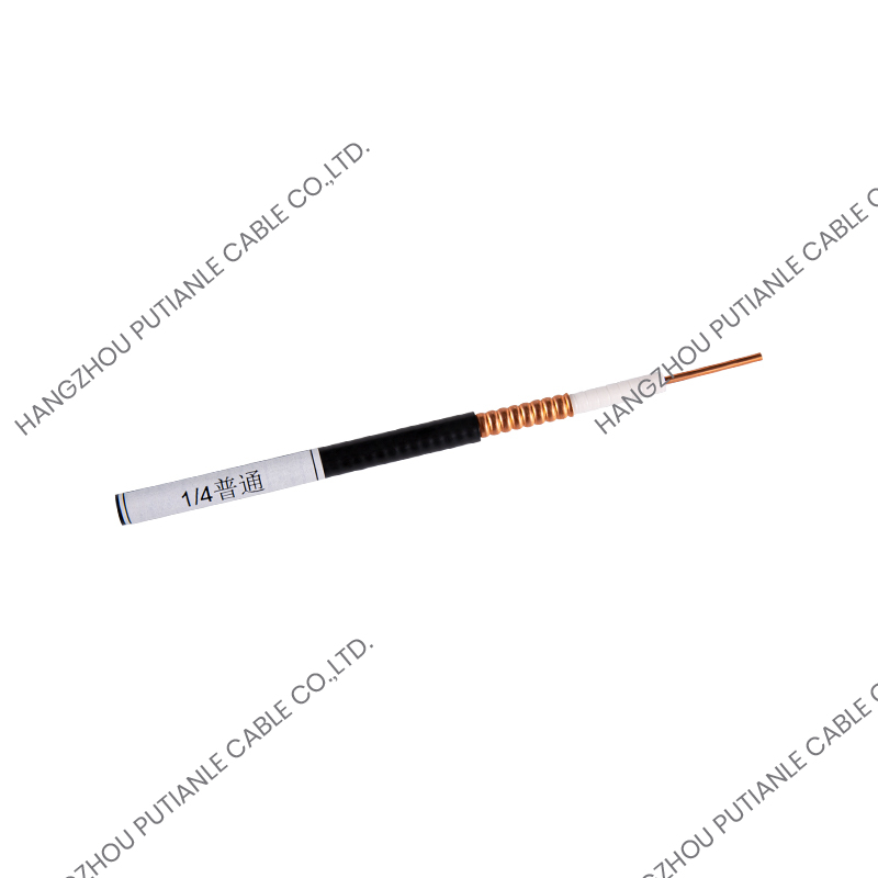
Corrugated Copper Tube Coaxial Cable: Construction and Advantages
Corrugated copper tube coaxial cable is the most technically significant and commercially important advancement in high-performance coaxial cable design. In this construction, the outer conductor is formed from a copper strip that is longitudinally folded into a tube and then mechanically corrugated — given a repeating helical or annular (ring) groove pattern along its length — before the outer jacket is applied. The corrugation transforms what would otherwise be a rigid smooth tube into a cable that retains the superior electrical shielding effectiveness and low-loss characteristics of a solid copper outer conductor while gaining the ability to be flexed, coiled, and installed around corners and obstacles.
The mechanical principle behind corrugation is analogous to a bellows or a corrugated metal hose: the alternating ridges and valleys in the copper tube wall allow the cable to bend by compressing the corrugations on the inside of the curve and expanding them on the outside, distributing the bending stress across many small deformations rather than concentrating it at a single point. This allows corrugated copper tube coaxial cables to achieve minimum bend radii of 5 to 10 times the cable outer diameter — significantly better than smooth tube alternatives — while maintaining the continuous copper outer conductor that is essential for high shielding effectiveness and low signal attenuation.
Helical vs. Annular Corrugation Patterns
Corrugated copper tube coaxial cables are manufactured with either helical or annular corrugation patterns, and the choice between them affects both the cable's mechanical behavior and the connector termination method. Helical corrugation — in which a single continuous groove spirals along the length of the outer conductor like a screw thread — provides superior flexibility and allows the cable to flex repeatedly in multiple planes without fatigue cracking. Helically corrugated cables are preferred for installation routes with multiple bends and for applications involving periodic repositioning. Annular corrugation — in which a series of independent ring grooves encircle the outer conductor at regular intervals — provides greater crush resistance and is generally used in larger diameter, higher power cables where mechanical protection is a greater priority than repeated flexing.
Electrical Performance of Corrugated Copper Tube Cable
From an electrical standpoint, corrugated copper tube coaxial cable delivers performance that approaches or equals the best smooth tube constructions in most practical parameters. Shielding effectiveness values of 120 dB or greater are routinely achieved, meaning that signal leakage and external interference are attenuated to negligible levels. Attenuation values for a typical 50 ohm corrugated copper tube cable of 1-5/8 inch outer diameter are approximately 1.5 to 2.5 dB per 100 meters at 1 GHz, falling to under 1 dB per 100 meters at 100 MHz — figures that make these cables viable for runs of several hundred meters in cellular base station feeders, broadcast transmitter installations, and distributed antenna systems. Average power handling capacities for the same cable range from 5 kW to over 30 kW depending on frequency and cooling conditions, enabling their use in high-power FM and TV broadcast transmitters.
Braided Shield Coaxial Cable
Braided shield coaxial cable is the most widely produced and consumed coaxial cable type globally, found in consumer electronics, test and measurement equipment, CCTV systems, cable television distribution, and countless other applications. In this construction, the outer conductor is formed by weaving multiple fine copper or copper-alloy wire strands in a diagonal braid pattern over the dielectric insulator. The braid provides a flexible, continuous conductive layer that can be bent, coiled, and routed through tight spaces without damage, and it also serves as the return current path and electromagnetic shield.
The key limitation of braided shield construction compared to solid or corrugated tube designs is shielding effectiveness. A single braid layer typically achieves shielding effectiveness of 55 to 75 dB — substantially lower than the 100 dB or more achievable with solid or corrugated copper tube outer conductors. This is because the woven structure inherently contains small gaps between the wire strands through which electromagnetic energy can pass. Double-braid and triple-braid constructions improve shielding effectiveness to 85 to 90 dB at the cost of increased weight and reduced flexibility, but still do not match the performance of tube-based outer conductors. For applications in strong interference environments or where signal confidentiality requires very high shielding levels, braided cable is generally inadequate and corrugated or foil-plus-braid constructions are specified instead.
Foil Shield and Foil-Plus-Braid Coaxial Cable
Foil shield coaxial cables use a thin layer of aluminum or copper foil — typically bonded to a polyester film carrier for mechanical support — wrapped around the dielectric as the outer conductor. The foil provides 100 percent coverage of the dielectric surface with no gaps, which gives it theoretically superior shielding effectiveness compared to single-braid designs at high frequencies, particularly above 1 GHz where the braid's apertures become a more significant fraction of a wavelength. However, foil-only constructions are fragile and cannot carry significant return current without resistance heating, making them suitable only for signal-level applications rather than power transmission.
The most effective flexible cable construction for applications requiring both high shielding and flexibility is the foil-plus-braid combination, in which a foil layer provides full coverage and a braid layer applied over it provides structural integrity, current-carrying capacity, and additional shielding at lower frequencies where the foil alone is less effective. This construction achieves shielding effectiveness values of 90 to 100 dB and is widely used in satellite receiver downleads, precision measurement cables, and data center interconnects where both shielding performance and installation flexibility are required simultaneously.
Semi-Rigid and Conformable Coaxial Cable
Semi-rigid coaxial cable uses a solid copper tube outer conductor — similar in material to smooth tube feeder cable but in much smaller diameters — that can be formed to a specific shape using bending tools but retains that shape permanently after forming. It cannot be bent by hand without risking damage to the outer conductor or dielectric spacing. Semi-rigid cable is used almost exclusively within electronic equipment enclosures, RF modules, and microwave assemblies where extremely precise impedance control, near-perfect shielding, and minimal connector-to-connector signal path length are required. It is available in outer diameters from 0.047 inches to 0.250 inches and is the standard interconnect medium in microwave circuit assemblies, radar systems, and satellite communication hardware.
Conformable coaxial cable is a development of semi-rigid cable that uses a stranded or wound outer conductor — rather than a solid tube — to provide hand-formability while retaining the electrical characteristics of semi-rigid construction. It can be bent by hand to a minimum radius of approximately three times the cable outer diameter and holds its shape after bending without springback, making it suitable for prototype assemblies and field installations where the routing path is not known in advance and cannot be pre-formed in a workshop environment.
Coaxial Cable Types Compared: Key Parameters
The following table summarizes the most important distinguishing characteristics of each major coaxial cable type to support application-based selection decisions.
| Cable Type | Outer Conductor | Shielding (dB) | Flexibility | Power Handling | Typical Use |
| Smooth Copper Tube | Solid smooth tube | >120 dB | None | Very high | Fixed high-power feeder runs |
| Corrugated Copper Tube | Corrugated copper tube | >120 dB | Good | Very high | Cellular, broadcast, DAS feeders |
| Single Braid | Woven wire braid | 55–75 dB | Excellent | Low to moderate | Consumer electronics, CCTV, CATV |
| Double Braid | Two braid layers | 85–90 dB | Very good | Moderate | Military, industrial RF |
| Foil + Braid | Foil layer + braid | 90–100 dB | Good | Low to moderate | Satellite, data centers, precision RF |
| Semi-Rigid | Solid copper tube (small diameter) | >120 dB | None (form-once) | Moderate | Microwave assemblies, radar modules |
| Conformable | Wound or stranded tube | 100–110 dB | Good (hand-formable) | Moderate | Prototypes, field RF assemblies |
Where Corrugated Copper Tube Coaxial Cable Is Specified
Corrugated copper tube coaxial cable occupies a unique position in the market because it is the only construction that simultaneously delivers the electrical performance of a solid copper outer conductor — including very high shielding effectiveness, low attenuation, and high power handling — with sufficient flexibility for practical field installation. This combination makes it the standard specification in several demanding application categories.
- Cellular base station antenna feeders: The antenna feeder cables connecting base station transceivers to rooftop or tower-mounted antennas in 4G and 5G networks are almost universally corrugated copper tube coaxial cable, typically in 1/2 inch, 7/8 inch, or 1-5/8 inch standard sizes. The cables must route through cable trays, around corners, and through building penetrations while handling kilowatts of transmitter power and maintaining minimal signal loss over runs of 20 to 100 meters or more.
- FM and television broadcast transmitter feeders: High-power FM radio and digital television transmitters require feeder cables capable of handling continuous average powers of 5 kW to 80 kW or more at frequencies from 87.5 MHz to 862 MHz. Corrugated copper tube cables in diameters from 1-5/8 inch to 6-1/8 inch are the standard solution for these applications worldwide.
- Distributed antenna systems (DAS): In-building wireless coverage systems for large venues — airports, stadiums, hospitals, and shopping centers — use corrugated copper tube cable as the main trunk feeder between the signal source and the distributed antenna points throughout the building, where its low loss over long runs is critical for maintaining adequate signal level at remote antenna locations.
- Military and government communication infrastructure: Fixed military communication sites and government broadcast facilities specify corrugated copper tube coaxial cable for its combination of high shielding effectiveness — which supports TEMPEST requirements for electromagnetic emissions security — and long-term mechanical reliability in permanently installed infrastructure expected to remain in service for decades.
- Particle accelerator and scientific research facilities: High-energy physics research installations use corrugated copper tube coaxial cable for RF power distribution to accelerating cavities, where precise impedance control, very high power levels, and minimal signal reflections are simultaneously required over complex cable routing paths through the accelerator structure.
Selecting the Right Coaxial Cable Type for Your Application
Choosing between coaxial cable types requires a structured evaluation of the application's electrical, mechanical, and environmental requirements. The following parameters should be defined before specifying a cable type, as each one may eliminate certain constructions from consideration or make a specific type the clear optimal choice.
- Operating frequency range: Higher frequencies demand lower-attenuation cable. For frequencies above 500 MHz over runs longer than 30 meters, corrugated copper tube or high-quality foil-plus-braid constructions are typically required to keep signal loss within system budget. Braided cable is generally adequate for sub-100 MHz applications over short runs.
- Power handling requirement: For applications involving more than 500 W of continuous average power, copper tube outer conductor designs — either smooth or corrugated — are the only practical options. Braided and foil constructions cannot handle significant power without overheating the outer conductor.
- Required shielding effectiveness: Applications in high-interference environments, sensitive measurement systems, or facilities with emissions security requirements need shielding effectiveness above 100 dB, which effectively mandates corrugated or solid copper tube construction rather than braid-based designs.
- Installation flexibility and routing complexity: Complex cable routes with multiple bends in different planes require flexible cable. Corrugated copper tube cable is the best choice when both high performance and installation flexibility are needed simultaneously. Braided cable provides greater flexibility but at the cost of lower electrical performance.
- Environmental exposure: Outdoor installations require UV-resistant and weatherproof outer jackets, and cables in areas subject to mechanical impact need armored or heavy-wall jacket constructions. Corrugated copper tube cables with polyethylene or low-smoke halogen-free jackets are specifically engineered for outdoor feeder applications in all climate zones.


