中文简体
中文简体 English
 Español
Content
- 1 The Four Layers That Give Coax Its Name
- 2 Why the Concentric Structure Beats Two Parallel Wires
- 3 Characteristic Impedance: The Number That Determines Compatibility
- 4 Attenuation, Frequency, and Skin Effect
- 5 Braided or Corrugated: Choosing the Right Outer Conductor
- 6 Connectors, Jumpers, and the Complete Transmission Path
A site engineer replacing a damaged feeder line on a rooftop base station faces the same question as a system integrator quoting a CCTV job: why does one cable deliver clean signal while another of the same length produces flicker, errors, or reflected power? The short answer is that a coaxial cable works as a controlled transmission line. Its concentric assembly of inner conductor, dielectric, outer conductor, and jacket guides a high-frequency electromagnetic wave along a defined path, keeps interference out, and gives the line a predictable characteristic impedance. Once the relationship between these layers is clear, every number on a datasheet — impedance, attenuation, shielding class, bending radius — starts to make practical sense.
The Four Layers That Give Coax Its Name
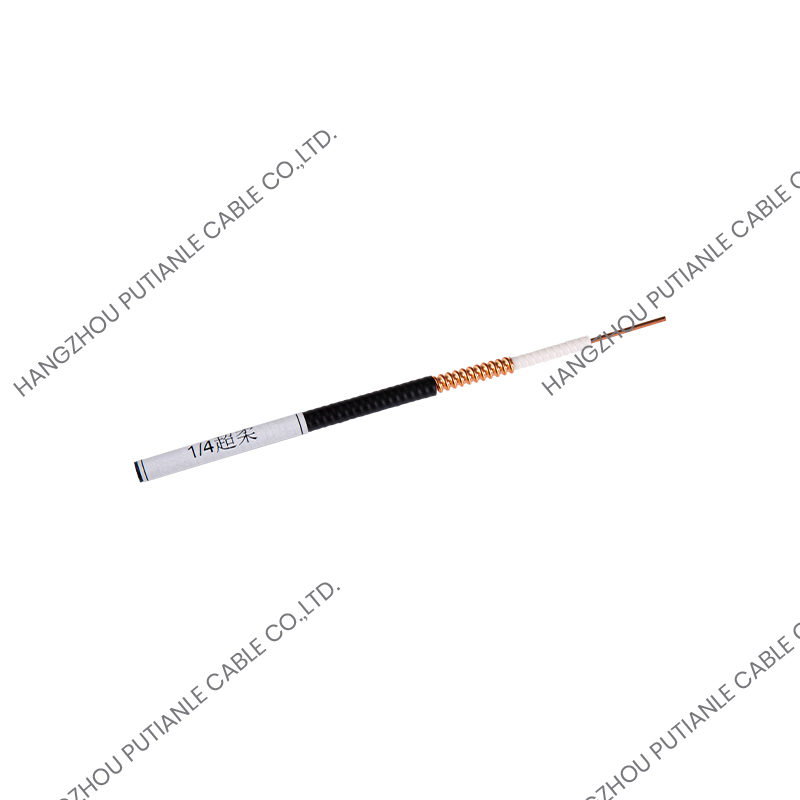
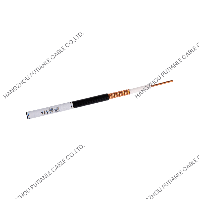
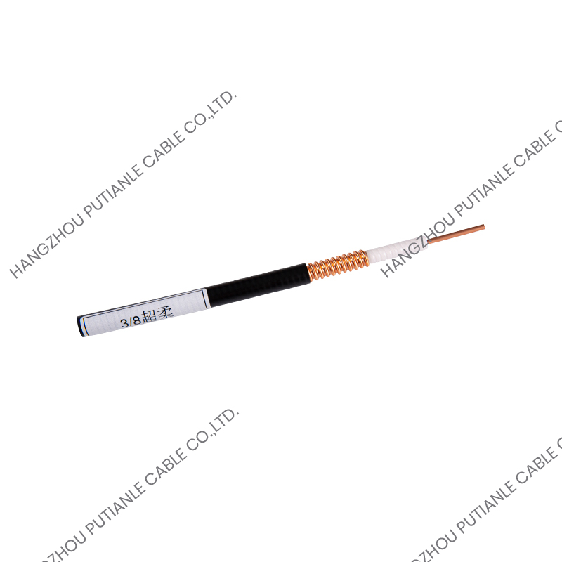
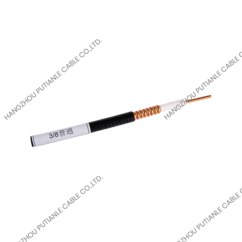
The word coaxial refers to two conductors that share the same geometric axis. Strip back any coax and the same four layers appear in the same order:
- Center conductor: solid copper, copper-clad steel, or copper-clad aluminum. It carries the forward signal current, and its diameter is one of the main factors that set the cable's impedance and attenuation.
- Dielectric: a foam or solid polyethylene layer that keeps the inner and outer conductors at a precise spacing. Because the electromagnetic wave travels mostly through this material, its density and uniformity directly control signal velocity and loss.
- Outer conductor: a braid, foil laminate, or corrugated metal tube. It provides the return path for the signal and acts as the shield that keeps interference out and signal in.
- Jacket: a PE or PVC cover that protects the assembly from moisture, UV light, abrasion, and mechanical stress.
Nothing else in the cable performs the electrical work. Individual series differ in conductor material, dielectric formulation, braid density, and shield structure, but the operating principle stays the same.
Why the Concentric Structure Beats Two Parallel Wires
An ordinary pair of wires can carry a signal, but not well at high frequency. The electric and magnetic fields spread around the wires, radiate energy, pick up noise, and shift when nearby objects move. Coax solves this by wrapping the signal path in a second conductor.
The forward signal travels on the center conductor, and the return current flows on the inner surface of the outer conductor. The electromagnetic field between the two conductors stays confined inside the dielectric. Because the outer conductor is continuous along the cable, external fields cannot easily penetrate it, and the cable's own field cannot radiate outward. That containment is what gives coax its low loss, strong noise immunity, and stable impedance over long runs.
This is also why the shield's construction matters more than many buyers assume. A dense braid or solid shield carries the return current uniformly and keeps the line balanced around its axis. A loose, thin shield — common on very cheap cable — raises the resistance of the return path and lets interference in when the cable is bent or routed next to power lines.
Characteristic Impedance: The Number That Determines Compatibility
Every coaxial cable has a characteristic impedance, normally 50 or 75 ohms, that describes the ratio of voltage to current in the traveling wave. This value is set at the factory by the ratio of the inner conductor diameter to the outer conductor inner diameter and by the dielectric constant of the insulation. It is not a resistance that can be measured with an ohmmeter; it is a property of the line geometry that determines how the signal propagates.
When the source, cable, connectors, and load all have the same impedance, the signal is absorbed cleanly. When one element is mismatched, part of the signal reflects back, reducing the level that reaches the receiver and creating ghosting on video or high VSWR and heating in RF transmitters. Keeping a single impedance all the way from the equipment port to the antenna or camera is the basic rule of coax installation.
| Impedance | Common applications | Typical outer conductor | Typical connectors |
|---|---|---|---|
| 50 ohms | RF feeder lines, base station antennas, wireless links, test equipment | Braided wire, corrugated copper, corrugated aluminum | N, DIN, 4310 |
| 75 ohms | Cable TV, CCTV video, broadband access, satellite IF | Braided wire, aluminum tube | F, BNC, RCA |
Attenuation, Frequency, and Skin Effect
At high frequencies, current does not flow uniformly through a conductor; it concentrates near the surface. Engineers call this the skin effect. It is why a thicker center conductor lowers loss, why copper outperforms steel and aluminum for low-attenuation designs, and why the surface quality of the outer conductor matters as much as its thickness. Part of the signal energy is also absorbed by the dielectric, so a low-density, moisture-resistant foam insulation keeps this loss small.
Every cable specification lists attenuation in decibels per 100 meters at specific frequencies. A loss figure might be low at 50 MHz and several times higher at a few gigahertz. The practical consequence is that for each cable size there is a maximum useful run length before a receiver, amplifier, or repeater is required. Long outdoor runs therefore favor cables with a larger conductor and a solid tube shield, while short indoor connections can use flexible braided constructions.
Braided or Corrugated: Choosing the Right Outer Conductor
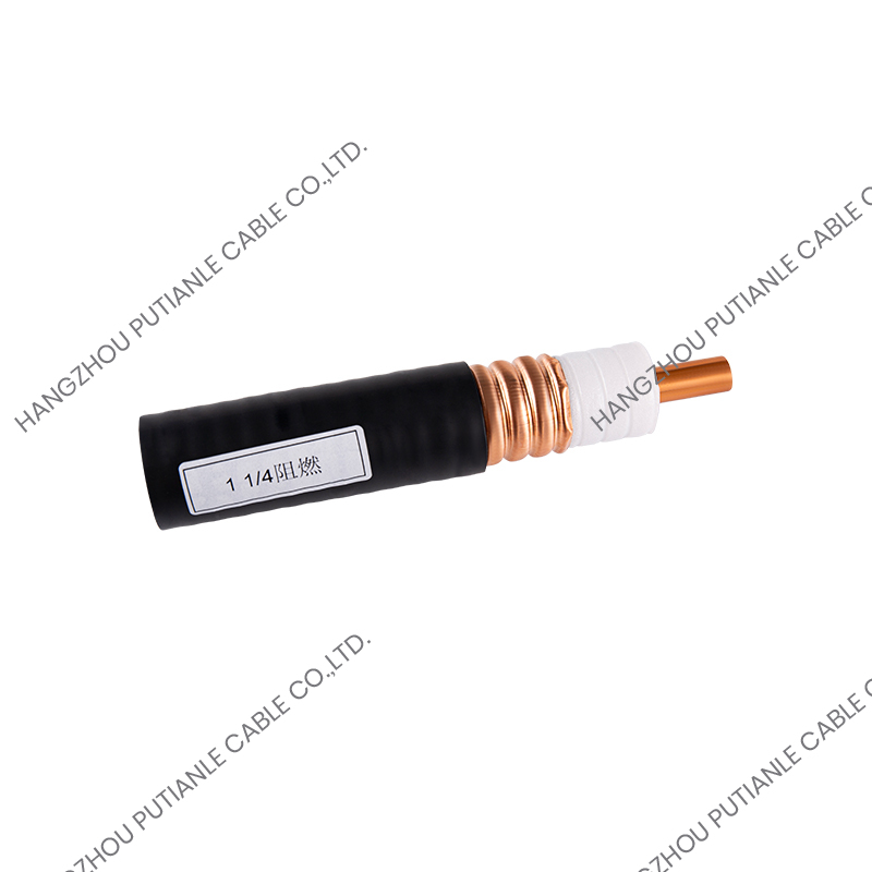
The choice between a braided and a corrugated outer conductor is the decision that most often separates a smooth installation from a service call. Braided outer conductors — used in RG-6, RG-213, RG-214, and the 50-ohm PTL series — flex easily, terminate quickly, and suit indoor and short-to-medium runs. Corrugated copper or aluminum tube conductors provide a continuous shield, lower attenuation, and much stronger protection against interference, at the cost of reduced flexibility and heavier hardware.
For CCTV and video distribution, a 75-ohm RG6 braided coaxial cable is often the most practical choice. It terminates quickly with compression connectors, handles the bandwidth of HD cameras, and installs cleanly through ceilings and conduit. If you are comparing different types for a project, a review of the main categories of RF coaxial cables helps map the naming conventions and performance families used across suppliers.
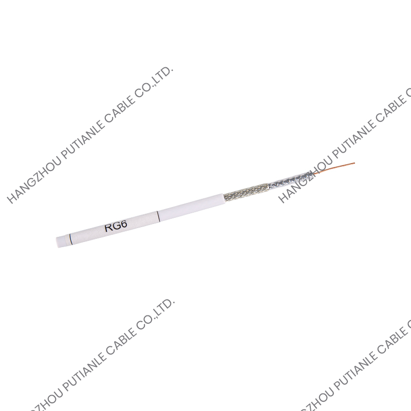 RG6 Simple Installation Outer Conductor 75 OHM Braiding Cable Manufacturers, CusHangzhou Putianle Cable Co., Ltd. is China Custom RG6 Simple Installation Outer Conductor 75 OHM Braiding Cable Manufacturers,Company,Int...View Product →
In a 50-ohm system, the equivalent choice for short, flexible interconnects is a 50-ohm PTL400 flexible braided cable. It sits between a thin patch cord and a stiff corrugated feeder, giving equipment racks and jumper runs the bendability they need without sacrificing the shielding that keeps a transmitter clean.
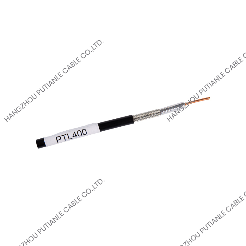 LMR400 Outer Conductor Braiding Coaxial Cables Manufacturers,CompanyPutianle Cable is China LMR400 Braiding Coaxial Cables Manufacturers, PTL400 Outer Conductor Braiding Cables Company,Wholesale PTL400 , L...View Product →
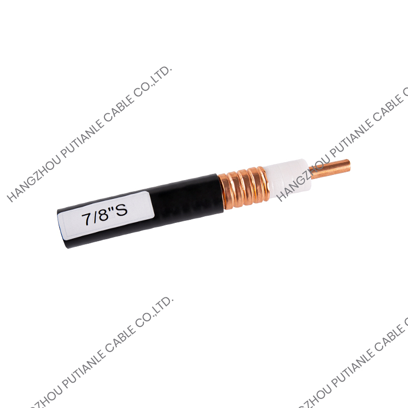
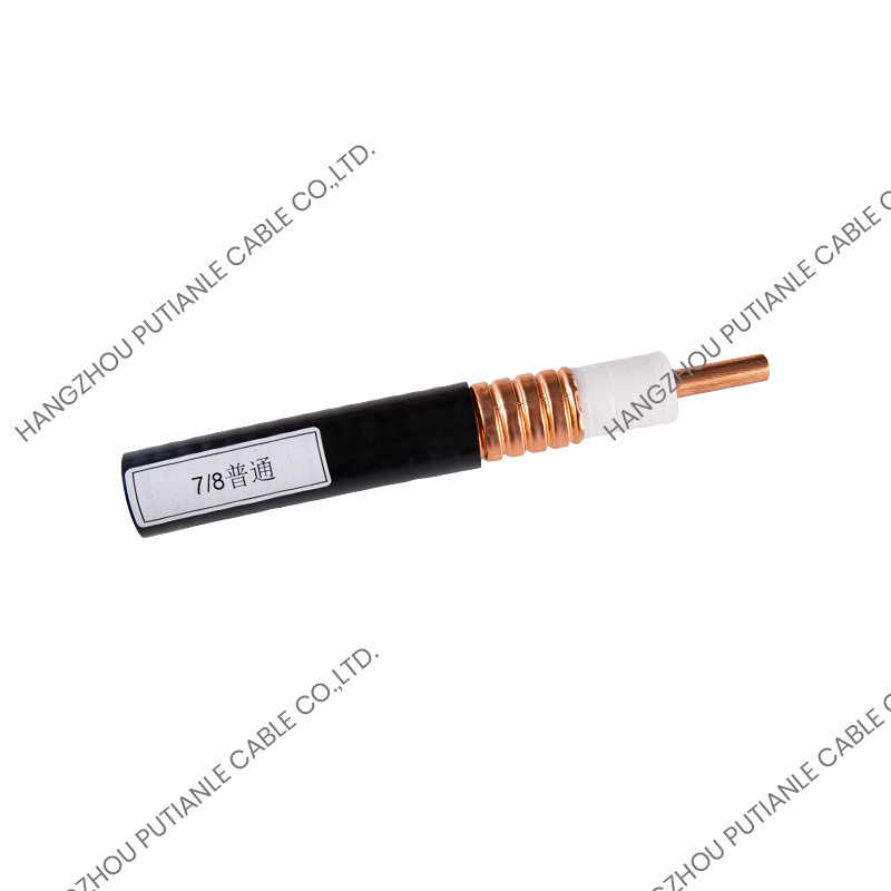
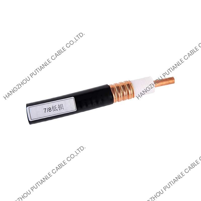
When the run crosses a rooftop or climbs a tower, the loss budget usually dictates the opposite construction. A 7/8-inch low-loss corrugated aluminum tube coaxial cable keeps the signal level up over the long vertical run and blocks interference far better than any braid of similar diameter. The trade-off is that the cable forms a permanent structure: it must be routed with generous bend radii and supported properly along its length.
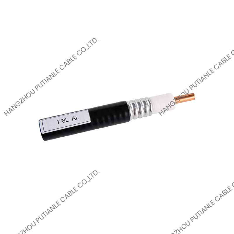 7/8" Low Loss Corrugated Aluminum Tube 50 Ohm Coaxial Cable Manufacturers, CustoHangzhou Putianle Cable Co., Ltd. is China Custom 7/8 inch Low Loss Corrugated Aluminum Tube 50 Ohm Coaxial Cable Manufacturers,Company,T...View Product →
Connectors, Jumpers, and the Complete Transmission Path
A coaxial cable is only as good as its terminations. A poor connector adds a discrete impedance discontinuity, reflects part of the signal, and can let moisture into a cable that would otherwise last years outdoors. Matching the connector family — N, DIN, or 4310 for 50-ohm systems; F or BNC for 75-ohm systems — to both the cable and the equipment is as important as choosing the cable itself.
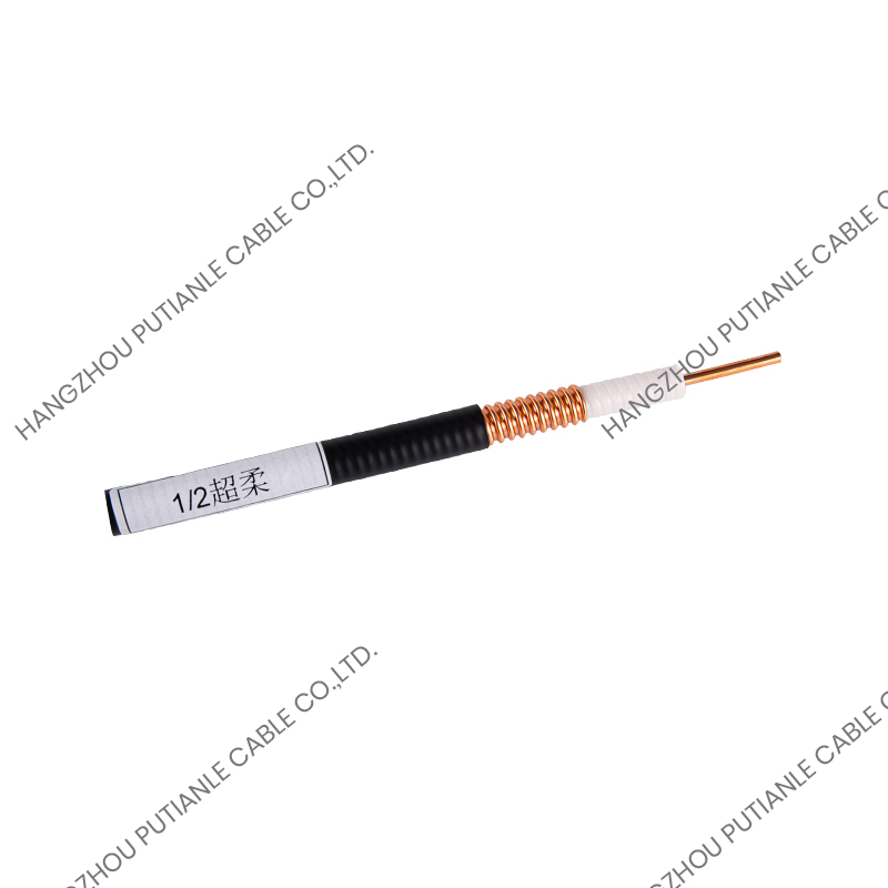
Pre-terminated jumpers are the standard way to connect a feeder to an antenna or a radio without carrying crimp tooling to the site. A jumper built with a 1/2-inch super-flexible cable preserves the bending freedom that a rigid feeder cannot provide. Keep jumpers short, respect their minimum bend radius, and remember that every adapter adds a small reflection to the path.
Coaxial cable works because it is a transmission line, not just two wires inside a tube. The geometry of the two concentric conductors sets the impedance; the shield determines how cleanly the signal stays inside; and the choice of materials and construction sets the loss that limits the run length. Reading a datasheet against this background converts the numbers into installation decisions: which impedance matches the system, which shield blocks the noise at the site, and which construction fits the route the cable has to follow.