
 中文简体
中文简体 English
 Español
Content
- 1 What Are 75 Ohm Braiding Cables?
- 2 Why 75 Ohms: The Physics Behind the Standard
- 3 Construction of a 75 Ohm Braided Coaxial Cable
- 4 Common 75 Ohm Braided Cable Types and Their Applications
- 5 Braid Coverage and Shielding Effectiveness Explained
- 6 Signal Attenuation and Maximum Run Lengths
- 7 Selecting the Right 75 Ohm Braided Cable for Your Application
- 8 Installation Best Practices for 75 Ohm Braided Cables
What Are 75 Ohm Braiding Cables?
75 ohm braiding cables are coaxial cables engineered to maintain a characteristic impedance of 75 ohms along their entire length, with a braided metal shield surrounding the dielectric and center conductor. The 75 ohm impedance value is the industry standard for video signal transmission, broadcast infrastructure, cable television distribution, and satellite systems. The braided shield — constructed from interwoven strands of tinned copper, bare copper, or aluminum — provides the electromagnetic shielding that prevents external interference from corrupting the signal and stops the cable from radiating energy into surrounding equipment.
Understanding what makes a 75 ohm braided coaxial cable perform reliably requires looking at both the impedance specification and the shielding construction together. The impedance determines how efficiently the cable transfers signal energy from source to load without reflection losses. The braid determines how effectively the cable protects that signal from the electromagnetic environment around it. Both factors matter in professional installations, and selecting the wrong specification for either leads to measurable signal degradation in real systems.
Why 75 Ohms: The Physics Behind the Standard
The 75 ohm impedance standard is not arbitrary. It originates from the physical relationship between a coaxial cable's geometry and its signal transmission properties. In a coaxial cable, the characteristic impedance is determined by the ratio of the outer conductor's inner diameter to the inner conductor's outer diameter, and by the dielectric constant of the insulating material between them. Mathematical analysis of coaxial transmission lines shows that 75 ohms represents the impedance at which a solid polyethylene dielectric cable achieves minimum signal attenuation — meaning the lowest loss per unit length for a given cable diameter.
This minimum-loss characteristic makes 75 ohm cables the optimal choice for distributing video signals over the long cable runs common in broadcast facilities, CATV trunk lines, and building distribution systems. When the source impedance, cable impedance, and load impedance are all matched at 75 ohms, signal reflections are eliminated and maximum power transfer occurs. Any impedance mismatch in the signal path creates reflections — visible as ghosting in analog video or packet errors in digital transmission — which is why maintaining the 75 ohm match from connector to connector throughout an installation is a fundamental installation requirement.
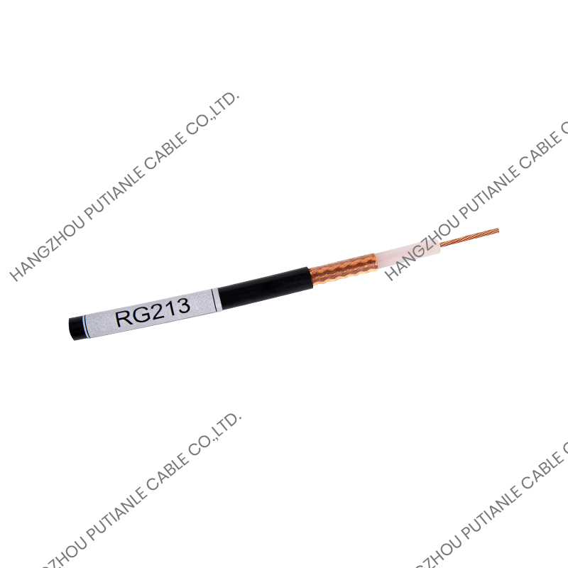
Construction of a 75 Ohm Braided Coaxial Cable
A 75 ohm braided coaxial cable is built in concentric layers, each serving a specific electrical or mechanical function. From the center outward, the layers are as follows.
Center Conductor
The center conductor carries the signal. It is typically a solid or stranded copper wire, sometimes silver-plated to reduce resistive losses at high frequencies where the skin effect concentrates current at the conductor surface. Solid conductors provide lower resistance and are standard in fixed installations. Stranded conductors improve flexibility for applications involving repeated movement or tight bending radii, such as patch cables and camera cable assemblies.
Dielectric Insulator
Surrounding the center conductor is the dielectric — the insulating material that physically separates the inner and outer conductors while establishing the electrical conditions that determine impedance. Solid polyethylene (PE) and foam polyethylene are the most common dielectric materials in 75 ohm cables. Foam PE has a lower dielectric constant than solid PE, which reduces signal velocity reduction and lowers attenuation at high frequencies, making foam dielectric cables the standard choice for high-frequency video and RF applications above 1 GHz.
Braided Shield
The braided shield is woven directly over the dielectric from fine wire strands, typically 0.1 mm to 0.2 mm in diameter, arranged in a helical interlocking pattern. The density of the braid — expressed as percentage optical coverage — is the critical shielding parameter. A braid with 85% optical coverage leaves visible gaps between strands that allow low-frequency interference to enter. A braid with 95% or higher coverage is standard for professional video cables, providing effective shielding from low MHz frequencies up through the UHF band. Some high-performance 75 ohm cables use a foil layer beneath the braid to achieve near-100% coverage at high frequencies where braid alone becomes less effective.
Outer Jacket
The outer jacket protects the internal structure from mechanical damage, moisture, and chemicals. PVC is standard for indoor applications, offering adequate flexibility and flame resistance. Low-smoke zero-halogen (LSZH) jackets are required in plenum spaces and public buildings in many jurisdictions. Polyethylene jackets provide superior UV and moisture resistance for direct burial and outdoor aerial applications. Jacket color is often used as a quick identification indicator — black for outdoor or general use, white for in-wall residential, orange for specific broadcast applications.
Common 75 Ohm Braided Cable Types and Their Applications
The 75 ohm braided cable family includes several standardized types optimized for specific frequency ranges, installation environments, and signal formats. The table below outlines the most widely used types:
| Cable Type | Outer Diameter | Frequency Range | Typical Application |
| RG-6 | 6.9 mm | Up to 3 GHz | Residential CATV, satellite dish drops, antenna feeds |
| RG-59 | 6.1 mm | Up to 1 GHz | CCTV, composite video, short analog video runs |
| RG-11 | 10.3 mm | Up to 1 GHz | Long CATV trunk runs, aerial distribution |
| HD-SDI (SMPTE 694M) | 6.1–6.9 mm | Up to 3 GHz | Broadcast HD video, studio routing, OB vans |
| 3G-SDI (SMPTE 424M) | 6.1–7.0 mm | Up to 6 GHz | 1080p broadcast, digital cinema, live production |
| 12G-SDI | 6.5–7.3 mm | Up to 12 GHz | 4K UHD broadcast, single-link 4K routing |
Braid Coverage and Shielding Effectiveness Explained
Braid coverage percentage is the most commonly cited shielding specification, but it tells only part of the story. Optical coverage — the percentage of the underlying dielectric surface visually covered by the braid — is relatively easy to measure and correlates well with low-frequency shielding effectiveness below 100 MHz. At these frequencies, the gaps in the braid are small relative to the wavelength of the interference, so a 95% coverage braid provides adequate protection for most interference sources encountered in building environments.
At higher frequencies — above 500 MHz and into the GHz range — the gaps in even a high-coverage braid become significant relative to the wavelength of potential interference. This is where the combination of braid plus foil (sometimes called "quad-shield" in consumer cables or "foil-braid" in professional grades) provides substantially better performance. The foil provides continuous 100% coverage at high frequencies while the braid provides the mechanical durability and low-resistance ground connection that foil alone cannot sustain. For 3G-SDI and 12G-SDI broadcast cables, foil-plus-braid construction is effectively mandatory to meet the return loss and shielding specifications required by SMPTE standards.
Shielding effectiveness is quantified in decibels of attenuation applied to interference attempting to enter or exit the cable. A well-constructed 75 ohm braided cable with foil-plus-braid shielding achieves shielding effectiveness of 85 dB or higher across a broad frequency range, which is sufficient to meet the requirements of EMC-regulated broadcast and telecommunications environments. Cables rated only to 60–70 dB shielding effectiveness are generally not suitable for professional video installations where adjacent cables, power wiring, and RF equipment create persistent interference fields.
Signal Attenuation and Maximum Run Lengths
Attenuation — the loss of signal level as it travels along the cable — increases with frequency and cable length. Every 75 ohm cable has an attenuation specification measured in dB per 100 meters at specific frequencies. This specification directly determines the maximum practical cable length for a given signal format. Exceeding the attenuation budget causes signal errors, timing jitter in digital systems, and visual artifacts or sync failures in video applications.
As a practical reference, a standard RG-6 cable with foam dielectric has an attenuation of approximately 11 dB per 100 meters at 200 MHz. HD-SDI at 1.485 Gbps typically tolerates a cable attenuation up to about 20 dB before the receiver's cable equalizer reaches its compensation limit, giving a practical maximum run of around 150–180 meters on good-quality RG-6. For 3G-SDI at 2.97 Gbps, the higher frequency content of the signal reduces the usable run length to approximately 80–100 meters on the same cable. 12G-SDI on a standard RG-6 equivalent may be limited to 30–50 meters depending on the cable construction and the quality of the receiver's equalizer circuitry.
Selecting the Right 75 Ohm Braided Cable for Your Application
Choosing the correct 75 ohm braided cable requires matching the cable's frequency performance, physical construction, and environmental rating to the specific demands of the installation. The following considerations apply to most professional and commercial projects:
- Signal format and frequency: Identify the highest frequency component of your signal. Analog composite video peaks around 6 MHz; HD-SDI content extends to 750 MHz; 3G-SDI to 1.5 GHz; 12G-SDI to 6 GHz. The cable's rated frequency range must exceed your signal's highest frequency component with margin.
- Run length: Calculate total cable length including any patch bays, connectors, and passive splitters in the signal path. Each connector and passive device adds insertion loss. Build in a safety margin of at least 20% below the cable's theoretical maximum distance.
- Shielding requirement: For broadcast and professional AV environments, specify cables with foil-plus-braid shielding and a minimum shielding effectiveness of 85 dB. For residential CATV or CCTV, standard single-braid RG-6 is adequate in most cases.
- Installation environment: Specify PVC jacket for standard indoor runs, LSZH for plenum and public spaces, PE or direct-burial rated jacket for outdoor and underground installations. Never substitute indoor-rated cable in outdoor or plenum environments regardless of cost savings.
- Flexibility requirements: Fixed permanent installations use solid-center-conductor cables for lowest attenuation. Camera drops, patch bays, and frequently disturbed cables require stranded or flex-rated center conductors to prevent work hardening and center conductor breakage over time.
- Connector compatibility: Confirm that the cable's outer diameter and dielectric dimensions are compatible with the connectors you intend to crimp or solder. RG-6 and RG-59 have different outer diameters and require different connector body sizes — using the wrong connector results in unreliable mechanical termination and impedance discontinuities at the joint.
Installation Best Practices for 75 Ohm Braided Cables
Even a correctly specified cable will underperform if installed improperly. Maintaining the cable's impedance and shielding integrity through the installation process requires attention to bending radius, termination quality, and routing practice. The minimum bend radius for most 75 ohm coaxial cables is approximately ten times the cable's outer diameter — for a 7 mm RG-6 cable, this means bends should not be tighter than 70 mm radius. Bending tighter than the minimum radius deforms the dielectric, displaces the center conductor from the geometric center of the outer conductor, and permanently changes the local impedance at the bend point, introducing a reflection into the signal path that cannot be corrected after installation.
Termination quality is equally important. Poor connector installation — inadequate braid preparation, center conductor not fully seated, dielectric trimmed to the wrong length — creates impedance discontinuities and shielding gaps at the most critical point in the cable assembly. For broadcast SDI applications, all connectors should be verified with a time-domain reflectometer (TDR) after installation to confirm that return loss meets the system specification at each termination point. For CATV and residential systems, a signal level meter sweep confirms that the installed loss matches the calculated budget before commissioning the system.


