
 中文简体
中文简体 English
 Español
Content
- 1 Understanding 50 Ohm Braiding Cable
- 2 The Construction of a 50 Ohm Braiding Cable
- 3 Why 50 Ohms? The Physics Behind the Standard
- 4 Common 50 Ohm Braiding Cable Types and Specifications
- 5 Shielding Effectiveness and Braid Coverage
- 6 Primary Applications of 50 Ohm Braiding Cable
- 7 How to Select the Right 50 Ohm Braiding Cable
Understanding 50 Ohm Braiding Cable
A 50 ohm braiding cable is a type of coaxial cable engineered to maintain a characteristic impedance of 50 ohms throughout its entire length. This specific impedance value is not arbitrary — it represents an optimized balance between two competing electrical parameters: power handling capacity and signal attenuation. In practical terms, 50 ohm coaxial cables are the industry standard for radio frequency (RF) transmission systems, test and measurement equipment, military communications, wireless infrastructure, and a wide range of industrial electronics applications where reliable, low-loss signal transmission is critical.
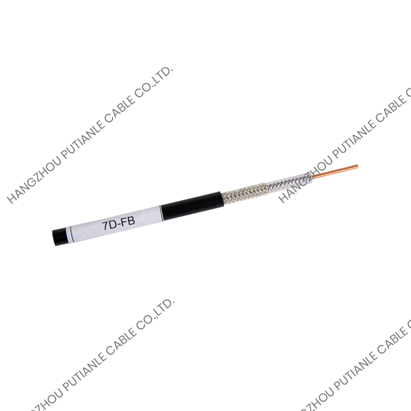
The term "braiding" refers specifically to the construction of the cable's outer conductor, which consists of fine metal wires woven in a crosshatched, braided pattern around the dielectric insulation layer. This braided shield is one of the defining structural features of the cable and plays a central role in determining its shielding effectiveness, flexibility, and overall electrical performance. Understanding how the braid is constructed, what materials are used, and how the braid coverage percentage affects performance is essential for making informed cable selection decisions.
The Construction of a 50 Ohm Braiding Cable
Every 50 ohm braiding cable is built from the inside out, with each layer contributing to the cable's final impedance, shielding performance, and mechanical durability. The four primary layers are the center conductor, the dielectric insulation, the braided shield, and the outer jacket.
Center Conductor
The center conductor carries the RF signal and is typically made from bare copper, tinned copper, silver-plated copper, or copper-clad aluminum (CCA). Solid conductors offer lower resistance and better high-frequency performance, while stranded conductors provide greater flexibility for installations that require repeated bending or movement. The diameter of the center conductor is one of the key variables that determines the cable's characteristic impedance — along with the dielectric material and outer conductor diameter — so it is precisely controlled during manufacturing.
Dielectric Insulation
Surrounding the center conductor is the dielectric insulation layer, which electrically isolates the inner conductor from the outer shield and controls the propagation velocity of the signal. Common dielectric materials include solid polyethylene (PE), foam polyethylene, expanded PTFE (polytetrafluoroethylene), and solid PTFE. Foam and expanded dielectrics have lower dielectric constants than solid materials, which reduces signal attenuation at high frequencies and increases propagation velocity. PTFE dielectrics are used in high-temperature and military-grade applications due to their excellent thermal stability and chemical resistance.
Braided Shield
The braided outer conductor is what distinguishes braiding cable from foil-shielded or spiral-wound alternatives. It is formed by weaving multiple strands of fine wire — typically tinned copper, bare copper, or silver-plated copper — in an interlocking diamond pattern around the dielectric. The braid coverage percentage, which typically ranges from 85% to 98% in high-quality cables, directly determines how effectively the shield blocks electromagnetic interference (EMI) from entering or leaving the cable. Higher braid coverage provides better shielding effectiveness but also increases the cable's stiffness and cost. Some premium cables combine a foil layer with a braid to achieve both high-frequency shielding and structural integrity.
Outer Jacket
The outer jacket protects the cable from mechanical damage, moisture, chemicals, and UV exposure. Common jacket materials include PVC (polyvinyl chloride) for standard indoor use, low-smoke zero-halogen (LSZH) compounds for enclosed spaces with fire safety requirements, polyurethane for flexible outdoor or industrial installations, and fluoropolymers such as FEP or PTFE for extreme temperature or chemical environments.
Why 50 Ohms? The Physics Behind the Standard
The choice of 50 ohms as the standard impedance for RF power transmission cables has a well-established physical basis. For an air-dielectric coaxial cable, the impedance that minimizes signal attenuation is approximately 77 ohms, while the impedance that maximizes power handling capacity is approximately 30 ohms. The value of 50 ohms sits roughly in the geometric mean of these two figures, providing a practical compromise that serves both goals reasonably well.
This compromise made 50 ohm cables the dominant choice for transmitting and receiving RF signals in systems where both power efficiency and signal integrity matter — including transmitters, amplifiers, antennas, and test instruments. The 75 ohm standard, by contrast, is optimized for minimum signal loss in receive-only applications such as cable television and broadcast systems, where power handling is less important than achieving the lowest possible noise figure over long cable runs.
Impedance matching is critical in RF systems because any mismatch between the source impedance, cable impedance, and load impedance causes signal reflections. These reflections reduce the power delivered to the load, create standing waves on the cable, and can damage transmitting equipment operating at high power levels. Using a 50 ohm cable to connect 50 ohm-rated equipment ensures that maximum power is transferred with minimum reflection loss.
Common 50 Ohm Braiding Cable Types and Specifications
There are dozens of standardized 50 ohm coaxial cable types, each designed for specific frequency ranges, power levels, and environmental conditions. The most widely used types in commercial and professional applications include the following:
| Cable Type | Outer Diameter | Attenuation at 1 GHz | Typical Use |
| RG-58 | 4.95 mm | ~0.85 dB/m | Short RF links, antenna feeds |
| RG-213 | 10.3 mm | ~0.37 dB/m | Amateur radio, base station feeds |
| LMR-400 | 10.3 mm | ~0.22 dB/m | Cellular, wireless LAN, outdoor runs |
| LMR-200 | 4.95 mm | ~0.50 dB/m | Indoor RF distribution, jumpers |
| RG-316 | 2.49 mm | ~1.50 dB/m | Test equipment, military, tight spaces |
| RG-402 (semi-rigid) | 3.58 mm | ~0.69 dB/m | Microwave assemblies, instrumentation |
Larger diameter cables such as LMR-400 and RG-213 offer significantly lower signal attenuation per unit length than smaller cables like RG-58, making them the preferred choice for longer cable runs where maintaining signal strength is critical. Smaller, more flexible cables are better suited for short interconnects, portable equipment, and installations where space and bend radius are limiting constraints.
Shielding Effectiveness and Braid Coverage
The braided shield is the most performance-critical structural element of a 50 ohm braiding cable, and its design directly determines how well the cable isolates its internal signal from external electromagnetic interference and prevents internal signal radiation that could cause interference to nearby systems.
Braid coverage is expressed as a percentage of the dielectric surface covered by the interwoven wire strands. At 85% coverage, small gaps between the wire crossings allow some signal leakage and reduce low-frequency shielding effectiveness. At 95% to 98% coverage — achievable with denser weave patterns or double-braid constructions — the gaps are minimized, and the shielding effectiveness can reach 90 dB or higher across a wide frequency range. For applications operating in electromagnetically noisy environments, such as industrial facilities, medical equipment rooms, or military platforms, high-coverage or double-braided cables are strongly recommended.
Some specialized 50 ohm cables use a combination of a bonded aluminum foil layer beneath the outer braid. The foil provides near-100% theoretical coverage at high frequencies, while the braid adds mechanical strength and provides a reliable termination point for connectors. This hybrid shield construction achieves the best overall shielding performance across the widest frequency range.
Primary Applications of 50 Ohm Braiding Cable
The 50 ohm standard is deeply embedded across a wide range of industries and technology sectors. Its applications span from consumer electronics to mission-critical communications infrastructure.
- Wireless telecommunications: Base station antenna feeders, tower-mounted amplifier connections, and inter-unit jumpers in cellular networks (2G through 5G) almost universally use 50 ohm coaxial cables. Low-loss types like LMR-400 or 7/8-inch foam dielectric cables are standard for these high-power, high-frequency installations.
- RF test and measurement: Vector network analyzers, spectrum analyzers, signal generators, and power meters are all designed around 50 ohm impedance, and the cables connecting them must maintain that impedance precisely. Phase-stable, low-reflection cables with high-quality braided shields are essential in lab environments.
- Military and defense: Military communications systems, radar, electronic warfare equipment, and avionics rely on 50 ohm cables built to MIL-SPEC standards with PTFE dielectrics and silver-plated conductors for reliability across extreme temperature and environmental ranges.
- Amateur radio (ham radio): Antenna feed lines and transceiver-to-antenna connections in amateur radio stations use 50 ohm cables because virtually all amateur radio transceivers are designed with a 50 ohm output impedance.
- Medical devices: Ultrasound imaging probes, RF ablation systems, and MRI-compatible signal transmission components use 50 ohm coaxial assemblies where shielding and signal integrity directly affect diagnostic accuracy and patient safety.
- Data acquisition and industrial sensors: High-speed data acquisition systems, oscilloscope probes, and industrial RF sensors use 50 ohm coaxial connections to ensure clean signal transmission with minimal reflections and noise pickup.
How to Select the Right 50 Ohm Braiding Cable
Choosing the correct 50 ohm braiding cable for a specific application requires evaluating several interdependent parameters. No single cable type is optimal for all situations, and the wrong choice can result in excessive signal loss, mechanical failure, or electromagnetic compatibility problems.
- Operating frequency range: Higher frequencies require cables with lower dielectric constant materials and precise dimensional control. Always check the cable's published attenuation-vs-frequency curve and verify it meets your system's requirements at the highest operating frequency.
- Cable length and acceptable signal loss: Calculate the total insertion loss for your cable run at the operating frequency. If the attenuation exceeds your system's budget, select a larger diameter, lower-loss cable type or consider adding an in-line amplifier.
- Power handling requirement: Transmit applications require cables rated for the peak and average power levels of the transmitter. Exceeding the cable's power rating causes dielectric heating, impedance shift, and potentially cable damage or fire.
- Environmental conditions: For outdoor, underground, or extreme-temperature installations, select cables with UV-resistant jackets, waterproof constructions, or high-temperature dielectric materials rated for the expected operating environment.
- Flexibility and bend radius: In installations requiring repeated flexing — such as robotic arms, moving equipment, or portable instruments — choose cables with stranded center conductors and flexible jacket compounds rated for continuous flex cycle applications.
- Connector compatibility: Ensure the cable's outer diameter and braid construction are compatible with the connector series being used. Common 50 ohm connector types include N-type, SMA, BNC, TNC, and 7-16 DIN, each suited to different frequency ranges and power levels.
Selecting the right 50 ohm braiding cable is a decision that directly affects the reliability, efficiency, and longevity of any RF system it is part of. By carefully matching cable construction, attenuation characteristics, shielding performance, and environmental ratings to the specific demands of the application, engineers and system integrators can ensure consistent signal integrity from installation through the full service life of the system.


