
 中文简体
中文简体 English
 Español
Content
- 1 What Exactly Is a 75 Ohm Aluminum Tube Cable?
- 2 How Is a 75 Ohm Aluminum Tube Cable Constructed?
- 3 What Are the Key Electrical Specifications to Understand?
- 4 Where Is 75 Ohm Aluminum Tube Cable Typically Deployed?
- 5 How Do You Select the Right Cable for Your Application?
- 6 What Are the Most Common Installation Mistakes to Avoid?
- 7 How Does Aluminum Tube Cable Compare to Other 75 Ohm Cable Options?
What Exactly Is a 75 Ohm Aluminum Tube Cable?
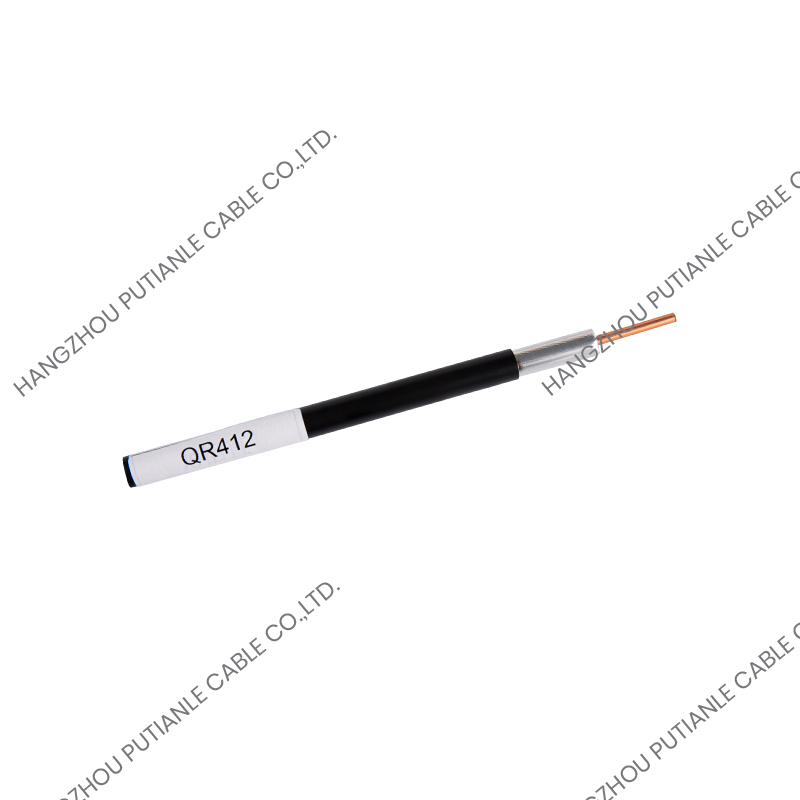
A 75 ohm aluminum tube cable is a type of coaxial cable specifically engineered to maintain a characteristic impedance of 75 ohms throughout its length, using a hollow or corrugated aluminum tube as its outer conductor. Unlike standard coaxial cables that use braided copper or foil shielding, the aluminum tube construction provides a rigid, continuous, and highly effective outer conductor that offers superior shielding effectiveness, lower signal attenuation at high frequencies, and excellent mechanical protection. This design makes it particularly well-suited for broadcast television distribution, cable television (CATV) trunk lines, satellite signal transport, and other applications where signal integrity over long distances is critical.
The 75 ohm impedance value is the internationally adopted standard for video and RF signal transmission systems. It represents the optimal balance between minimum signal attenuation and maximum power handling in a coaxial cable of practical dimensions. When the cable's impedance matches the source and load impedance, reflections are minimized and signal power is transferred efficiently. The aluminum tube outer conductor, combined with a foam or solid dielectric and a solid or stranded center conductor, ensures this impedance is maintained consistently across the cable's operating frequency range.
How Is a 75 Ohm Aluminum Tube Cable Constructed?
Understanding the internal construction of this cable type helps engineers and installers make informed decisions about which product best fits their system requirements. Each component plays a specific role in achieving the cable's electrical and mechanical performance.
Center Conductor
The center conductor is typically a solid copper or copper-clad aluminum (CCA) wire. Solid copper offers the best conductivity and is preferred for shorter runs and high-frequency applications. Copper-clad aluminum reduces the cable's overall weight, which is advantageous in aerial installations. The diameter of the center conductor is precisely calculated relative to the dielectric and outer conductor dimensions to achieve the target 75 ohm impedance.
Dielectric Material
Surrounding the center conductor is a dielectric insulator, most commonly cellular (foam) polyethylene or solid polyethylene. Foam polyethylene has a lower dielectric constant than solid PE, which reduces signal velocity loss and lowers attenuation per unit length. This makes foam dielectric the preferred choice for trunk cables operating at frequencies above 1 GHz, such as those used in modern DOCSIS 3.1 broadband networks.
Aluminum Tube Outer Conductor
The defining feature of this cable type is its aluminum outer conductor. It may be constructed as a smooth-wall aluminum tube, a corrugated aluminum tube, or a longitudinally welded aluminum tape. Corrugated designs provide flexibility while maintaining the electrical properties of a solid tube, making them easier to route through conduits and around bends. The smooth-wall version offers slightly lower attenuation and is used where flexibility is less critical. The aluminum tube provides shielding effectiveness exceeding 120 dB, far superior to braided constructions, effectively preventing signal ingress or egress.
Outer Jacket
The assembly is completed with an outer jacket, typically made from black polyethylene (PE) or low-smoke zero-halogen (LSZH) compound. The jacket protects the aluminum tube from mechanical damage, moisture ingress, and UV degradation. For direct burial and aerial applications, UV-stabilized and moisture-resistant jacket formulations are specified to ensure long service life in outdoor environments.
What Are the Key Electrical Specifications to Understand?
Selecting the correct 75 ohm aluminum tube cable for a specific application requires a clear understanding of the key electrical parameters. These figures vary between cable sizes and manufacturers, but the following table illustrates typical values for commonly used trunk cable sizes:
| Cable Size (Series) | Outer Diameter (approx.) | Attenuation at 1 GHz (dB/100m) | Velocity of Propagation |
| RG-11 / QR-540 | 13.5 mm | ~8.5 dB | 87% |
| QR-715 (500 series) | 18.1 mm | ~5.5 dB | 87% |
| QR-860 (750 series) | 22.0 mm | ~4.2 dB | 87% |
| QR-1125 (1000 series) | 28.6 mm | ~3.0 dB | 87% |
Attenuation increases with frequency and decreases with cable diameter. For trunk and feeder network design, the cable size is selected based on the maximum allowable signal loss between amplifier stations. Larger diameter cables allow longer amplifier spacing, reducing the number of active components in the network and improving overall system noise performance. Velocity of propagation around 87% is typical for foam dielectric constructions and must be accounted for when calculating electrical delay in time-sensitive distribution systems.
Where Is 75 Ohm Aluminum Tube Cable Typically Deployed?
This cable type has a well-established presence in several demanding signal distribution environments. Its use is not limited to a single industry; rather, its properties make it suitable across multiple infrastructure sectors where reliable high-frequency signal transport is required.
CATV and HFC Network Infrastructure
Hybrid fiber-coaxial (HFC) networks form the backbone of cable television and broadband internet delivery to homes and businesses. In these networks, optical fiber carries signals from the headend to fiber nodes, after which 75 ohm aluminum tube trunk cables distribute the RF signal across neighborhoods to individual subscriber tap points. The superior shielding of the aluminum tube construction prevents signal leakage that would interfere with over-the-air spectrum users and prevents external interference from entering the network — both of which are regulatory requirements in most jurisdictions.
Broadcast Facility Signal Distribution
Television broadcast facilities use 75 ohm aluminum tube cable in their main distribution frames, equipment rooms, and inter-building connections where maintaining precise impedance matching across the full broadcast frequency range is essential. In studio environments, the mechanical rigidity of the aluminum tube construction also provides physical protection for critical signal paths that cannot tolerate interruption.
Satellite Ground Stations
Satellite ground stations require low-loss cabling between parabolic antennas and receiving equipment for frequencies typically ranging from 950 MHz to 2150 MHz in the L-band and up to 40 GHz in specialized systems. The low attenuation and excellent phase stability of aluminum tube cables make them well-suited for long cable runs between outdoor antenna structures and indoor equipment racks, where even small signal losses directly degrade the system's noise figure and link margin.
DAS and In-Building Cellular Systems
Distributed antenna systems (DAS) used to improve cellular coverage inside large buildings, stadiums, tunnels, and underground transit systems increasingly use 75 ohm and 50 ohm aluminum tube cables as their primary distribution medium. The high shielding effectiveness ensures that in-building signal distribution does not interfere with macro network planning, and the low loss per unit length minimizes the number of signal amplifiers required throughout the structure.
How Do You Select the Right Cable for Your Application?
Choosing the correct 75 ohm aluminum tube cable requires systematic evaluation of several technical and environmental factors. A cable that performs well in one application may be inappropriate in another, even if the impedance specification is identical.
- Operating frequency range: Confirm that the cable's rated frequency range covers your highest operating frequency with adequate margin. DOCSIS 3.1 systems extend to 1.2 GHz upstream and beyond 1 GHz downstream, requiring cables rated accordingly.
- Required attenuation budget: Calculate the maximum acceptable signal loss between amplifiers or active nodes and select a cable diameter that achieves the target span length within this budget.
- Installation environment: Aerial, direct burial, conduit, and indoor plenum applications each require specific jacket materials and UV or moisture resistance ratings. Confirm the cable specification matches the physical installation conditions.
- Flexibility requirements: Corrugated aluminum tube cables offer significantly better bending performance than smooth-wall designs. Where the route includes multiple bends or the cable must be pulled through conduit, corrugated construction reduces installation risk and labor cost.
- Connector compatibility: Aluminum tube cables require specialized compression or hardline connectors matched to the specific cable series and outer diameter. Mixing connector types or using mismatched tooling results in increased return loss and potential long-term reliability problems.
- Temperature rating: Installation in extreme climates, particularly for direct burial or aerial applications, requires verifying the cable's rated operating temperature range, typically from -40°C to +75°C for standard outdoor grades.
What Are the Most Common Installation Mistakes to Avoid?
Even high-quality 75 ohm aluminum tube cable will underperform if installation practices are incorrect. Field technicians and system designers should be aware of the following common pitfalls that degrade performance and shorten service life.
- Exceeding minimum bend radius: Aluminum tube cables have a defined minimum bend radius, typically 10–15 times the cable outer diameter. Bending beyond this limit permanently deforms the outer conductor, altering the local impedance and causing signal reflections.
- Improper connector preparation: The aluminum outer conductor must be cleanly cut and deburred before connector installation. Burrs or uneven cuts prevent the connector from seating correctly, increasing contact resistance and reflection at the junction.
- Moisture ingress at connectors: Outdoor connectors must be properly weatherproofed using self-amalgamating tape or manufacturer-supplied weatherproofing compounds after installation. Moisture entry at connector interfaces causes rapid corrosion of the aluminum conductor and progressive degradation of signal quality.
- Galvanic corrosion at support points: Aluminum reacts with dissimilar metals in the presence of moisture. Cable hangers and support hardware should be aluminum or stainless steel to prevent galvanic corrosion that can structurally weaken the outer conductor over time.
- Ignoring thermal expansion: Aluminum expands and contracts significantly with temperature changes. Aerial installations must incorporate adequate sag and expansion loops to prevent mechanical stress on connectors and cable supports during seasonal temperature cycling.
Following manufacturer installation guidelines, using calibrated torque tools for connector tightening, and conducting post-installation sweep testing with a cable analyzer are the most effective measures to ensure that the installed system achieves its designed performance from day one and maintains it throughout its operational life.
How Does Aluminum Tube Cable Compare to Other 75 Ohm Cable Options?
System designers often evaluate aluminum tube cable against quad-shield braided coaxial cable and fiber-fed node architectures. Each has its appropriate application domain. Quad-shield cables such as RG-6 and RG-11 offer greater flexibility and lower cost for short subscriber drop connections, but their braided shielding typically provides only 90–100 dB of shielding effectiveness — significantly less than the 120+ dB of aluminum tube construction. For trunk and distribution segments carrying multiple RF channels simultaneously over distances of 100 meters or more, aluminum tube cable delivers substantially lower attenuation and far better ingress protection, justifying its higher per-meter cost and more demanding installation requirements.
As fiber-deep and remote PHY architectures push optical fiber closer to subscribers in next-generation HFC networks, the role of aluminum tube trunk cable is evolving rather than disappearing. It continues to serve as the final coaxial segment connecting fiber nodes to distribution amplifiers and subscriber taps, and its proven performance, long deployment history, and extensive connector ecosystem make it likely to remain a fundamental component of broadband access infrastructure for the foreseeable future.


