
 中文简体
中文简体 English
 Español
Content
- 1 Understanding 50 Ohm Impedance in Braided Coaxial Cable
- 2 Physical Construction and Layer Functions
- 3 Common 50 Ohm Braiding Cable Series and Their Specifications
- 4 Key Electrical Performance Parameters
- 5 Primary Applications of 50 Ohm Braiding Cable
- 6 Installation Best Practices and Common Mistakes
- 7 Sourcing and Specification Checklist for Buyers
Understanding 50 Ohm Impedance in Braided Coaxial Cable
A 50 ohm braiding cable is a type of coaxial cable specifically engineered to maintain a characteristic impedance of 50 ohms along its entire length. Characteristic impedance is not a measure of DC resistance but rather a property that describes how the cable responds to high-frequency alternating signals — determined by the ratio of the cable's inductance per unit length to its capacitance per unit length. When a transmission line's characteristic impedance matches the impedance of the source and load it connects, signal reflections are eliminated, power transfer is maximized, and signal integrity is preserved across the operating frequency range.
The 50 ohm value is not arbitrary. It represents a carefully chosen engineering compromise between two competing factors: the impedance that minimizes signal attenuation in an air-dielectric coaxial line (approximately 77 ohms) and the impedance that maximizes power handling capacity (approximately 30 ohms). At 50 ohms, a coaxial cable achieves a practical balance between low loss and adequate power capacity, making it the de facto standard impedance for RF test equipment, telecommunications infrastructure, military electronics, and wireless communication systems worldwide. The braided outer conductor — a woven mesh of fine metallic wires — is the defining structural feature that gives these cables their mechanical flexibility, EMI shielding effectiveness, and characteristic appearance.
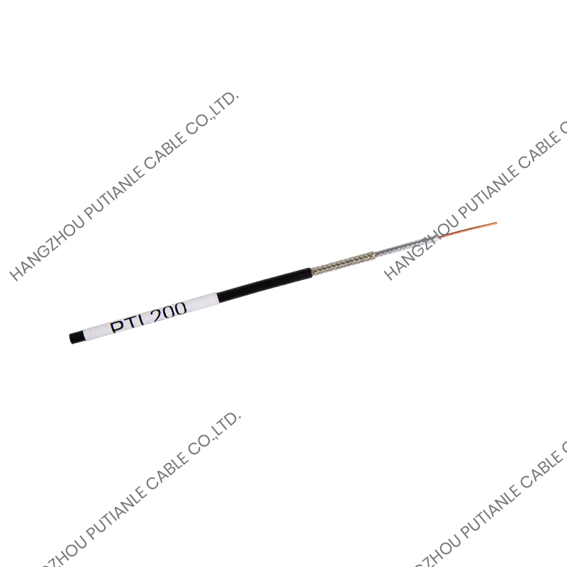
Physical Construction and Layer Functions
A 50 ohm braiding cable consists of four distinct concentric layers, each performing a specific electrical or mechanical function. Understanding the role of each layer is essential for selecting the correct cable for a given application and for diagnosing performance issues in installed systems.
Inner Conductor
The center conductor carries the RF signal current. It is typically constructed from bare copper, tinned copper, silver-plated copper, or copper-clad aluminum (CCA), depending on the application's requirements for conductivity, corrosion resistance, solderability, and weight. Solid conductors provide the lowest resistance and are used in semi-rigid and semi-flexible cables, while stranded conductors — consisting of multiple smaller wires twisted together — are used in flexible braiding cables to improve bend life and resistance to mechanical fatigue. The diameter of the inner conductor is a primary determinant of the cable's characteristic impedance, with the conductor-to-dielectric diameter ratio precisely controlled during manufacturing to achieve the target 50 ohm value.
Dielectric Insulation
The dielectric material surrounds the inner conductor and electrically isolates it from the outer braid. The dielectric's permittivity (dielectric constant) directly affects both the cable's characteristic impedance and its signal propagation velocity — expressed as the velocity of propagation (Vp) as a percentage of the speed of light in vacuum. Common dielectric materials include solid polyethylene (PE) with a dielectric constant of approximately 2.3, foam polyethylene with a lower effective dielectric constant of 1.4–1.6 that reduces signal attenuation, and polytetrafluoroethylene (PTFE) with excellent high-temperature stability and low loss characteristics suited to demanding RF applications. The choice of dielectric is a key differentiator between cable series and directly impacts insertion loss, power handling, and operating temperature range.
Braided Outer Conductor
The braided outer conductor is the defining structural element of this cable type. It consists of multiple strands of fine wire — typically tinned copper, bare copper, or silver-plated copper — woven in an interlocking diagonal pattern around the dielectric. The braid serves simultaneously as the return current path for the RF signal, the primary EMI shield preventing radiated emissions from the cable and protecting the signal from external electromagnetic interference, and the mechanical protective layer for the dielectric beneath it. Braid coverage — expressed as a percentage of the outer conductor surface that is covered by the woven wires — is a critical quality parameter. Coverage values of 85%, 90%, 95%, and 98% are commonly specified, with higher coverage providing better shielding effectiveness, particularly at lower frequencies where the braid's weave geometry is the dominant shielding mechanism.
Outer Jacket
The outer jacket encases the braid and provides mechanical protection, environmental sealing, and electrical insulation of the outer conductor from external conductors and ground planes. Jacket materials are selected based on the installation environment: polyvinyl chloride (PVC) for general indoor use with good flexibility and flame retardance; polyethylene (PE) for outdoor and direct burial applications requiring UV and moisture resistance; low-smoke zero-halogen (LSZH) compounds for confined spaces such as data centers, tunnels, and naval vessels where toxic gas emission during fire is a critical safety concern; and fluoropolymers such as FEP or PTFE for high-temperature or chemically aggressive environments.
Common 50 Ohm Braiding Cable Series and Their Specifications
The 50 ohm coaxial cable market is organized around a set of well-established cable series, each defined by a standardized combination of outer diameter, conductor size, dielectric type, and performance characteristics. The following table summarizes the most widely used series:
| Cable Series | Outer Diameter | Dielectric Type | Attenuation at 1 GHz | Typical Application |
| RG-58 | 4.95 mm | Solid PE | ~11.5 dB/100m | Test leads, patch cables, LAN |
| RG-174 | 2.54 mm | Solid PE | ~28 dB/100m | Portable devices, GPS antennas |
| LMR-195 | 4.95 mm | Foam PE | ~7.5 dB/100m | WiFi, cellular, short RF runs |
| LMR-400 | 10.29 mm | Foam PE | ~2.7 dB/100m | Base stations, long antenna runs |
| RG-142 | 4.95 mm | Solid PTFE | ~10 dB/100m | Aerospace, military, high-temp RF |
| RG-223 | 5.4 mm | Solid PE (double braid) | ~11 dB/100m | High-shielding EMC applications |
Key Electrical Performance Parameters
Selecting the correct 50 ohm braiding cable for a specific application requires evaluating several interdependent electrical performance parameters. Each parameter places a practical constraint on the cable's suitability for a given frequency range, installation distance, power level, or system sensitivity requirement.
- Insertion loss (attenuation): The reduction in signal power per unit length, expressed in dB/100m at a specified frequency. Attenuation increases with frequency due to the skin effect — where current flows increasingly near the conductor surface at higher frequencies, effectively reducing the conductor's cross-sectional area and raising its resistance. Foam dielectric cables consistently achieve lower attenuation than solid dielectric equivalents at the same outer diameter due to their lower effective permittivity.
- Velocity of propagation (Vp): The speed at which a signal travels through the cable expressed as a percentage of the speed of light in free space. For solid PE dielectric cables, Vp is typically 66%; for foam PE cables, Vp is 78–85%; for PTFE cables, Vp is approximately 69%. Vp directly affects electrical length calculations critical for phased array antenna design and time-domain measurements.
- Voltage Standing Wave Ratio (VSWR): A measure of impedance matching quality along the cable. A VSWR of 1.0:1 indicates perfect impedance matching with no reflections; practical cables are specified with VSWR values typically below 1.3:1 across their rated frequency range. Poor impedance control during manufacturing — caused by dimensional variation in conductor diameter or dielectric thickness — raises VSWR and increases reflected power.
- Shielding effectiveness: The ability of the braided outer conductor to prevent signal leakage from the cable (transfer impedance) and to reject external EMI ingress (screening attenuation). Specified in dB, shielding effectiveness depends on braid coverage percentage, wire diameter, weave angle, and frequency. Double-braid cables provide significantly better shielding — typically 90–100 dB isolation — compared to single-braid constructions at 60–85 dB.
- Maximum power rating: The maximum continuous RF power the cable can handle without exceeding the thermal limits of the dielectric material or the conductor. Power rating decreases with increasing frequency due to rising attenuation. Cable routing in confined spaces with restricted airflow further reduces effective power rating due to reduced thermal dissipation.
Primary Applications of 50 Ohm Braiding Cable
The 50 ohm standard permeates virtually every sector that uses RF signal transmission. The braided construction specifically enables applications requiring cable flexibility, repeated connection cycling, and installation in conduit or cable trays where semi-rigid alternatives would be impractical.
Wireless Communications Infrastructure
Cellular base stations, distributed antenna systems (DAS), WiFi access points, and private LTE networks all rely on 50 ohm braiding cable to connect radio units to antennas. In these installations, low insertion loss is the dominant selection criterion because every 0.1 dB of additional cable loss directly reduces the effective radiated power and receiver sensitivity of the system. LMR-400 and its equivalents are the standard choice for vertical runs in cell towers, while smaller-diameter cables such as LMR-195 are used for short jumper connections between equipment racks and antenna feed points.
RF Test and Measurement
Laboratory test environments use 50 ohm braiding cables as interconnects between signal generators, spectrum analyzers, network analyzers, power meters, and device under test (DUT) fixtures. Cables for test applications must combine low and stable insertion loss with excellent VSWR, phase stability under flexure, and long service life under repeated connection cycling. Silver-plated center conductors and PTFE dielectrics are commonly specified for test cables to ensure performance stability across the full calibrated frequency range of the test system, which may extend to 18 GHz, 26.5 GHz, or beyond in microwave test applications.
Military and Aerospace Electronics
Military and aerospace applications impose the most demanding requirements on 50 ohm braiding cable, combining wide operating temperature ranges (typically -55°C to +200°C), resistance to fuel, hydraulic fluid, and solvent exposure, high vibration and mechanical shock resistance, and compliance with military specifications such as MIL-DTL-17. PTFE-dielectric cables with silver-plated copper conductors and outer jackets of FEP or polyimide are standard in avionics, radar, electronic warfare, and satellite communication systems where performance reliability in extreme environments is mission-critical.
Industrial and Medical Instrumentation
Industrial automation systems, process control equipment, and medical imaging devices including MRI and ultrasound systems use 50 ohm braiding cable for sensor connections, signal routing within equipment enclosures, and interconnection between measurement modules. In medical applications, cable materials must comply with biocompatibility and cleanability requirements, and shielding effectiveness is critical for preventing EMI from corrupting sensitive diagnostic signals. The flexibility of braided cable construction is particularly valued in medical devices where cables must articulate with moving components or conform to ergonomic routing paths within equipment housings.
Installation Best Practices and Common Mistakes
Even the highest-quality 50 ohm braiding cable will underperform if installed incorrectly. The following practices ensure that the cable's specified performance is realized in the installed system:
- Always observe the cable's minimum bend radius specification — typically 10 times the outer diameter for flexible braiding cables during installation and 5 times the outer diameter for static bends. Exceeding the minimum bend radius distorts the dielectric cross-section, alters the local characteristic impedance, and can permanently damage the braid structure, increasing signal reflections and reducing shielding effectiveness.
- Use the correct connector type and termination technique for the cable series. Impedance discontinuities introduced by improperly prepared or mismatched connectors are a primary cause of system-level VSWR degradation. Follow connector manufacturer's preparation instructions precisely for center conductor trim length, dielectric trim length, and braid preparation to ensure the transition from cable to connector maintains 50 ohm continuity.
- Avoid overtightening cable ties or conduit fittings on installed coaxial cable. Radial compression of the cable deforms the dielectric and displaces the center conductor from the geometric axis, creating localized impedance anomalies that cause signal reflections. Use appropriate strain relief hardware rated for the cable's outer diameter.
- Verify installed cable performance using a vector network analyzer (VNA) or time-domain reflectometer (TDR) before system commissioning. Return loss and insertion loss measurements across the operating frequency range confirm that the cable and connector assembly meets the system's RF budget requirements and identifies any installation defects before they cause operational problems.
- For outdoor installations, ensure that all connector interfaces are weatherproofed using self-amalgamating tape or manufacturer-approved weatherproofing boots. Water ingress into connectors is the most common cause of premature RF performance degradation in outdoor antenna feed systems, as moisture in the connector interface rapidly oxidizes the conductor surfaces and dramatically increases contact resistance and insertion loss.
Sourcing and Specification Checklist for Buyers
When specifying or purchasing 50 ohm braiding cable for a project, buyers should compile a complete set of requirements covering electrical performance, mechanical properties, environmental conditions, and compliance obligations before approaching suppliers. Key parameters to define include the operating frequency range and maximum frequency, required attenuation budget per unit length, minimum shielding effectiveness, operating temperature range, jacket material and color, connector interface type if pre-terminated assemblies are required, applicable standards (MIL-DTL-17, IEC 61196, RoHS, REACH, UL listing), and minimum order quantity constraints for custom specifications.
Request production test data sheets or qualification test reports from prospective suppliers confirming that the offered cable meets the specified parameters across the full frequency and temperature range. For safety-critical or high-reliability applications, third-party testing against the applicable military or industrial standard provides an additional layer of assurance that cannot be verified from supplier-provided documentation alone. Investing time in thorough specification and supplier qualification at the procurement stage prevents costly field failures and system performance shortfalls that are far more expensive to correct after installation.


