
 中文简体
中文简体 English
 Español
Content
- 1 Why 50 Ohms? The Engineering Logic Behind the Standard
- 2 Construction of 50 Ohm Braiding Cable
- 3 Common Types of 50 Ohm Braiding Cable and Their Specifications
- 4 Key Electrical Parameters to Evaluate
- 5 Applications of 50 Ohm Braiding Cable
- 6 Practical Guidelines for Installing and Maintaining 50 Ohm Braiding Cable
- 7 Choosing the Right 50 Ohm Braiding Cable for Your Application
The 50 ohm braiding cable is one of the most widely deployed transmission line types in modern electronics, telecommunications, and RF engineering. Its characteristic impedance of 50 ohms represents a carefully considered engineering compromise — balancing signal attenuation, power handling capacity, and voltage breakdown performance in a single standardized value that has become the de facto standard for RF and microwave systems worldwide. Whether you are designing an antenna feed system, building a test bench, deploying a wireless network, or working with military communications equipment, understanding how 50 ohm braided coaxial cable is constructed, how it performs, and how to select the right variant for your application is essential to achieving reliable, low-loss signal transmission.
Why 50 Ohms? The Engineering Logic Behind the Standard
The choice of 50 ohms as a standard impedance is not arbitrary. It derives from a mathematical analysis of coaxial cable behavior in which two competing performance parameters are optimized simultaneously. For a coaxial cable with air dielectric, minimum signal attenuation per unit length occurs at approximately 77 ohms, while maximum power handling capacity occurs at approximately 30 ohms. The geometric mean of these two values falls close to 50 ohms, making it the practical sweet spot for systems that must simultaneously handle reasonable power levels while keeping signal losses manageable across a wide frequency range.
This 50 ohm standard was formally adopted by the military and subsequently embraced by the broader RF and electronics industry, which means that connectors, instruments, amplifiers, antennas, and test equipment are overwhelmingly designed and characterized around 50 ohm systems. This ecosystem-wide standardization is itself a powerful practical argument for using 50 ohm braiding cable — even in cases where a slightly different impedance might theoretically offer marginally better performance, the availability of components, the ease of system integration, and the wealth of published design data all favor the 50 ohm standard. The 75 ohm standard used in broadcast and consumer video applications is the only significant competitor, optimized specifically for minimum attenuation in that context.
Construction of 50 Ohm Braiding Cable
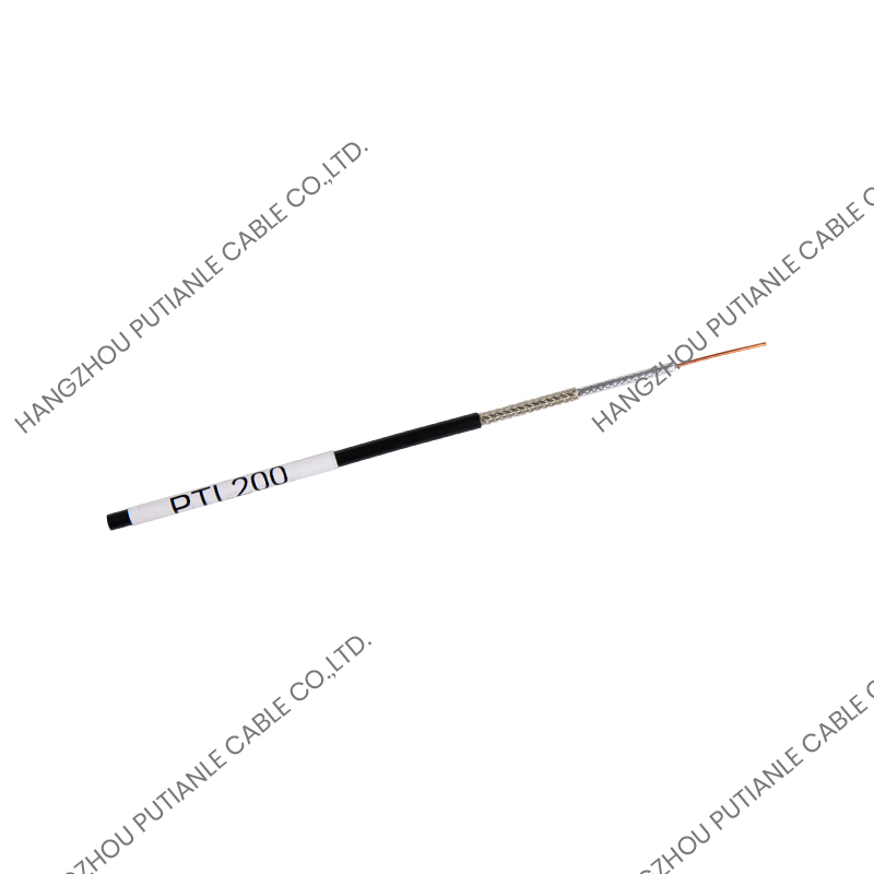
Understanding the physical construction of 50 ohm braided coaxial cable is fundamental to understanding its electrical performance, mechanical limitations, and environmental suitability. Every layer in the cable structure contributes to the overall impedance, loss, shielding effectiveness, and flexibility.
Inner Conductor
The inner conductor forms the core of the cable and is the primary signal-carrying element. It is typically made from bare copper, tinned copper, or silver-plated copper wire. Solid conductors offer lower DC resistance and are preferred for fixed installations where flexibility is not a concern. Stranded conductors — multiple fine wires twisted together — improve flexibility and fatigue resistance, making them better suited to applications involving repeated bending or movement. Silver-plated copper conductors are used in high-frequency applications where the skin effect concentrates current flow on the conductor surface, and the higher conductivity of silver at the surface reduces resistive losses at microwave frequencies.
Dielectric Insulation
The dielectric material surrounding the inner conductor determines the cable's velocity of propagation, its capacitance per unit length, and contributes significantly to signal attenuation through dielectric losses. Solid polyethylene (PE) is a traditional dielectric offering stable electrical properties and good moisture resistance. Foamed or cellular polyethylene introduces air voids into the dielectric, reducing its effective permittivity and improving both velocity factor and attenuation compared to solid PE. PTFE (polytetrafluoroethylene) dielectric is used in high-temperature and high-frequency applications because of its exceptionally low loss tangent and thermal stability up to 260°C. The dielectric dimensions, combined with the inner conductor diameter, are what physically set the cable's characteristic impedance at 50 ohms.
Braided Shield
The braided outer conductor is the defining structural element that gives braiding cable its name. It consists of multiple fine wires woven in an interlocking over-under pattern around the dielectric, forming a flexible tubular mesh that serves as both the return conductor and the electromagnetic shield. Braid coverage — expressed as a percentage of the surface area covered by the woven wires — is a critical specification. Coverage levels of 85–95% are typical for standard applications, while 95–98% coverage is used in high-shielding applications. Higher coverage reduces shield resistance and improves shielding effectiveness but also increases cable weight and stiffness. Some cables use a double braid — two concentric braided layers — for applications demanding superior EMI rejection, typically achieving shielding effectiveness values exceeding 90 dB across a wide frequency range.
Outer Jacket
The outer jacket protects the cable mechanically and environmentally. PVC jackets are common in general-purpose applications, offering flexibility and moderate UV and chemical resistance at low cost. PE jackets provide superior moisture resistance for outdoor and burial applications. LSZH (Low Smoke Zero Halogen) jackets are mandated in enclosed public spaces and plenum installations where combustion byproducts must be minimized. Fluoropolymer jackets such as FEP or PFA offer the broadest temperature range and chemical resistance, used in aerospace and industrial environments where standard jacket materials would degrade.
Common Types of 50 Ohm Braiding Cable and Their Specifications
The 50 ohm braiding cable market offers a wide range of standardized cable types, each optimized for a different balance of size, loss, power handling, and flexibility. The table below summarizes the most commonly used types and their key electrical and mechanical parameters.
| Cable Type | Outer Diameter | Attenuation @ 1 GHz | Max Frequency | Typical Applications |
| RG-58 | 4.95 mm | ~0.55 dB/m | 1 GHz | Lab use, ham radio, short runs |
| RG-8 / RG-213 | 10.3 mm | ~0.18 dB/m | 1 GHz | HF/VHF base stations, CB radio |
| LMR-400 | 10.29 mm | ~0.13 dB/m | 5.8 GHz | Cellular, Wi-Fi, antenna feedlines |
| LMR-200 | 5.38 mm | ~0.34 dB/m | 5.8 GHz | Wi-Fi patch cables, short antenna runs |
| RG-316 | 2.49 mm | ~1.05 dB/m | 3 GHz | Test leads, internal wiring, RF modules |
| RG-142 | 4.95 mm | ~0.49 dB/m | 3 GHz | Military, aerospace, high-temp environments |
| Ultraflex / Microwave Cable | Varies | Varies | Up to 65 GHz | Test & measurement, microwave systems |
RG-58 remains the most cost-effective option for short-run, low-frequency applications, but its relatively high attenuation makes it unsuitable for long cable runs above 100 MHz. LMR-400 has largely displaced RG-8 and RG-213 in modern installations due to its foamed dielectric construction that delivers lower attenuation in a similar form factor. RG-316 and RG-142, both using PTFE dielectric, fill the niche for compact, flexible, high-temperature-capable cables used in aerospace and instrumentation applications where physical size is as constrained as frequency range.
Key Electrical Parameters to Evaluate
Selecting a 50 ohm braiding cable based solely on its impedance value is insufficient — several additional electrical parameters must be evaluated against the requirements of the specific application to ensure the cable will perform reliably over its intended service life.
- Attenuation (Insertion Loss): Expressed in dB per unit length at a specified frequency, attenuation is perhaps the most practically important parameter for system budget calculations. It increases with frequency and cable length, and must be accounted for in link budget planning to ensure adequate signal level at the receiving end.
- Velocity Factor (VF): The velocity factor describes how fast the signal propagates through the cable relative to the speed of light in free space, typically ranging from 0.66 for solid PE dielectric to 0.85 or higher for foamed dielectric cables. This parameter is critical when cutting cable to a specific electrical length, such as when building quarter-wave transformers or phasing harnesses.
- Power Handling Capacity: Both average power (limited by thermal heating from resistive losses) and peak power (limited by voltage breakdown of the dielectric) must be verified for transmitting applications. At higher frequencies, average power handling drops significantly due to increased attenuation generating more heat per unit length.
- Shielding Effectiveness: Quantified in dB, shielding effectiveness measures the cable's ability to prevent external electromagnetic interference from coupling into the signal path and to prevent signal energy from radiating outward. This is particularly critical in dense RF environments, EMC-sensitive installations, and military or medical applications.
- VSWR and Return Loss: Voltage Standing Wave Ratio (VSWR) and return loss characterize how well the cable maintains its nominal 50 ohm impedance along its length. Poor impedance uniformity, caused by manufacturing inconsistencies or physical damage, creates reflections that degrade system performance.
- Capacitance per Unit Length: The distributed capacitance of the cable — typically 75–101 pF/m for 50 ohm cables — affects the cable's behavior at high frequencies and its interaction with source and load impedances in broadband systems.
Applications of 50 Ohm Braiding Cable
The 50 ohm braiding cable serves as the physical transmission backbone in an enormous range of applications spanning commercial, industrial, scientific, and military domains. Its versatility stems from the broad frequency range over which it maintains predictable, characterizable behavior and the mature ecosystem of compatible connectors and components that surrounds it.
Wireless and Cellular Infrastructure
In cellular base stations, distributed antenna systems (DAS), and Wi-Fi access point installations, 50 ohm braiding cable — typically LMR-400 or equivalent low-loss alternatives — connects transceivers to antennas across distances where signal loss must be tightly controlled. Every decibel of cable loss directly reduces effective radiated power and system range, making low-attenuation cable selection critical in these applications. In 5G deployments, where millimeter-wave frequencies impose severe attenuation penalties, minimizing cable run length and using the lowest-loss cable available within size constraints is an engineering priority.
Amateur Radio and Broadcast
Amateur radio operators rely heavily on 50 ohm coaxial cable for connecting transceivers to antennas across HF, VHF, and UHF bands. RG-8, RG-213, and LMR-400 are the dominant choices for outdoor antenna feedlines, valued for their combination of low loss and robust mechanical construction. In broadcast transmitter facilities, 50 ohm rigid or semi-rigid coaxial transmission lines handle high-power signals between transmitters and antenna systems, requiring cables rated for kilowatt-level continuous power handling.
Test and Measurement
RF test benches depend on 50 ohm braiding cable to interconnect spectrum analyzers, vector network analyzers, signal generators, power amplifiers, and devices under test. Phase stability under flexure is a particularly critical requirement in this context — cables used in precision measurements must maintain consistent electrical length even as they are repositioned, a requirement that specialized phase-stable cable constructions address through controlled conductor geometry and dimensionally stable dielectric materials. RG-316 and precision microwave cables are the workhorses of the test and measurement environment due to their compact size and broad usable frequency range.
Military and Aerospace
Military and aerospace applications impose the most demanding requirements on 50 ohm braiding cable, including operation across extreme temperature ranges from -65°C to +200°C, resistance to vibration and mechanical shock, immunity to fluids and fuels, and compliance with MIL-SPEC standards such as MIL-DTL-17. RG-142 with PTFE dielectric and double silver-plated copper braid is a common choice in these environments, meeting MIL-C-17 requirements while providing reliable performance in conditions that would rapidly degrade commercial-grade cables.
Practical Guidelines for Installing and Maintaining 50 Ohm Braiding Cable
Even the highest-quality 50 ohm braiding cable will underperform if installed incorrectly or subjected to avoidable mechanical stress. Following established installation best practices preserves the cable's impedance uniformity, shielding integrity, and long-term reliability.
- Respect the minimum bend radius: Each cable type has a specified minimum bend radius, typically 8–10 times the outer diameter for flexible cables and larger for semi-rigid types. Bending tighter than this limit deforms the dielectric and inner conductor geometry, altering the local impedance and creating a reflection point that degrades high-frequency performance.
- Use the correct connector termination technique: Improperly prepared or crimped connectors are the most common source of impedance discontinuities and signal leakage in installed cable systems. Follow connector manufacturer specifications for strip dimensions, and use the correct tooling — crimp tools, torque wrenches, and cable preparation tools — specified for the connector type and cable combination.
- Protect outdoor installations from moisture ingress: Water infiltrating the connector interface or jacket damage points is a leading cause of long-term cable degradation. Use self-amalgamating tape over outdoor connectors, specify direct-burial or gel-filled cables for underground runs, and inspect outdoor installations annually for jacket cracking or connector corrosion.
- Verify with a cable analyzer after installation: Before commissioning a cable run, measure return loss or VSWR across the operating frequency band using a vector network analyzer or cable fault locator. This confirms proper connector termination, absence of kinks or crush damage, and correct impedance continuity along the full cable length.
- Avoid running parallel to power cables: Where signal cables must be routed near AC power conductors, maintain a minimum separation of 100–150 mm and cross at right angles where possible to minimize inductive coupling and the risk of interference on the signal path.
Choosing the Right 50 Ohm Braiding Cable for Your Application
The final selection of a 50 ohm braiding cable should be driven by a clear, ranked set of application requirements rather than defaulting to the most familiar or most economical option. Start by establishing the operating frequency range and the maximum acceptable signal loss — these two parameters alone will eliminate many cable types from consideration. Then layer in environmental requirements: temperature range, UV exposure, chemical contact, and required jacket rating all constrain the viable material options further. Power handling requirements, physical flexibility needs, shielding performance mandates, and connector ecosystem compatibility each add additional constraint layers that collectively narrow the selection to a small set of appropriate cable types. In critical or long-service-life applications, the lifecycle cost of a higher-specification cable — including reduced maintenance, lower replacement frequency, and avoided system downtime — often justifies a significant premium over the lowest-cost option at the point of purchase.


