中文简体
中文简体 English
 Español
Content
- 1 The Four Core Components at a Glance
- 2 The Center Conductor: Where the Signal Actually Travels
- 3 The Dielectric: The Quiet Layer That Sets Impedance
- 4 The Outer Conductor and Shield: Return Path and Interference Control
- 5 The Jacket: Protection You Only Notice When It Fails
- 6 Connectors: The Component That Completes the Circuit
- 7 How Component Choices Shape Real-World Performance
- 8 What We Check Before a Coaxial Cable Leaves the Factory
Strip back the jacket of a coaxial cable and you find a cross-section that looks almost too simple to matter: a metal core, a ring of insulation, a metallic shield, and an outer jacket, all sharing one axis. That shared axis gives the cable its name, and it is also the reason the design has survived for decades in everything from cable television trunk lines to CCTV runs and antenna feeders.
The question of what the components of a coaxial cable really are comes up constantly in our daily work, because each of those layers has one job, and together they decide how much signal reaches the far end and how cleanly it arrives.
We are Hangzhou Putianle Cable, and we have been building these layers since 2003 in Lin'an, Zhejiang, a district widely known as China's cable hometown. Our 50-ohm and 75-ohm coaxial families, connectors and jumper assemblies have been installed in systems across more than 30 countries. Below we walk through each component the way we think about it on the factory floor. If you would like a wider view of how coaxial products are grouped before going layer by layer, our team keeps a short overview of the main categories of coaxial cable.
The Four Core Components at a Glance
Almost every coaxial cable, from a thin RG-6 patch lead to a rigid 1-5/8 inch feeder, is built from the same four elements arranged concentrically:
- Center conductor, which carries the radio frequency signal.
- Dielectric, which insulates the conductor and locks the spacing between the layers.
- Outer conductor or shield, which provides the return path and blocks interference.
- Jacket, which protects everything inside from moisture, abrasion and chemicals.
New engineers on our production lines get a one-page version of this. It looks like the table below, and it answers most of the questions we receive from buyers and system integrators.
| Component | Typical Materials | Primary Function |
|---|---|---|
| Center conductor | Solid bare copper, stranded copper, copper-clad steel | Carries the signal from end to end |
| Dielectric | Solid polyethylene, physical foam PE, PTFE | Maintains conductor spacing and sets impedance |
| Outer conductor | Copper braid, aluminum foil, corrugated copper or aluminum tube | Return path plus interference shielding |
| Jacket | PVC, PE, LSZH compounds | Mechanical and environmental protection |
The Center Conductor: Where the Signal Actually Travels
The center conductor is the first layer people picture, and it is the one most often oversimplified. Solid bare copper gives the lowest resistance and is the default for fixed installations. Stranded copper trades a little loss for flexibility, which matters when a cable is routed through moving equipment or repeatedly coiled during installation. Copper-clad steel appears in drop cables where tensile strength and cost carry more weight than the last fraction of a decibel.
Diameter matters as much as material. A larger conductor reduces attenuation, but it also forces a proportionally larger dielectric to hold the same characteristic impedance, so the whole cable grows stiffer and heavier. That trade-off is why our 50-ohm PTL and D-FB braiding series offer several gauges rather than a single universal size.
The Dielectric: The Quiet Layer That Sets Impedance
The dielectric does two jobs at once. It insulates the center conductor, and it holds a constant radial distance between the two conductors along the entire length of the cable. That constancy is what makes the cable a predictable transmission line instead of a random piece of metal.
Material choice changes performance noticeably. Solid polyethylene is stable and moisture resistant, which is why it dominates long outdoor runs. Physical foam polyethylene lowers the effective dielectric constant, raising velocity of propagation and reducing loss, but it is more sensitive to water ingress, so jacket integrity and bonding become critical. PTFE shows up in high-temperature and specialized applications where ordinary plastics would soften.
One detail worth remembering: characteristic impedance is fixed by the ratio between the inner diameter of the outer conductor and the outer diameter of the center conductor, together with the dielectric constant. Nothing about the impedance is set by the conductor alone.
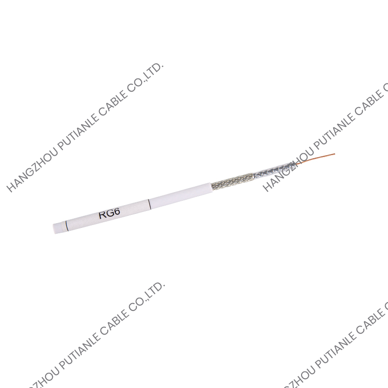 RG6 Simple Installation Outer Conductor 75 OHM Braiding CableIntroducing the RG6 Standard 75-Ohm Braiding Cable, a versatile and robust solution for a variety of communication needs. This cable is the quintessential choice for t...View Product →
The Outer Conductor and Shield: Return Path and Interference Control
Many people call this layer the shield, but it is really the second conductor of the circuit. Signal current travels down the center conductor and returns along the inner surface of the outer conductor. Its second duty is shielding: keeping external noise out and keeping the signal in, which is what limits radiation and crosstalk in densely cabled racks.
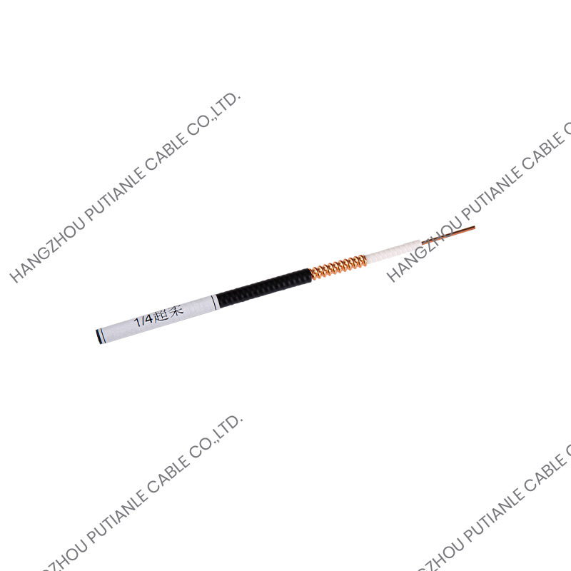
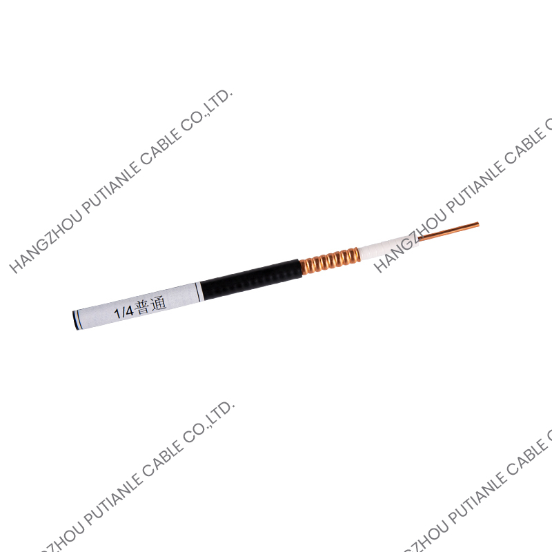
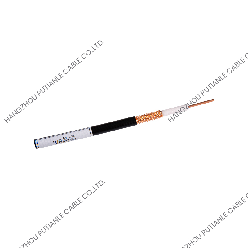
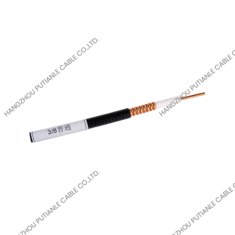
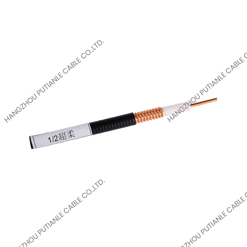
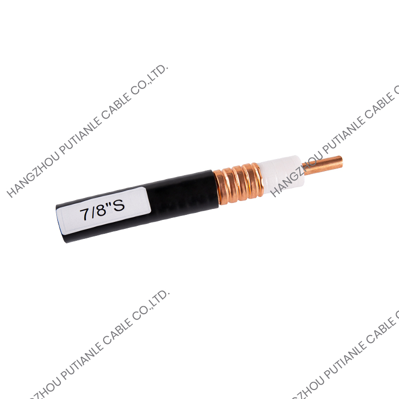
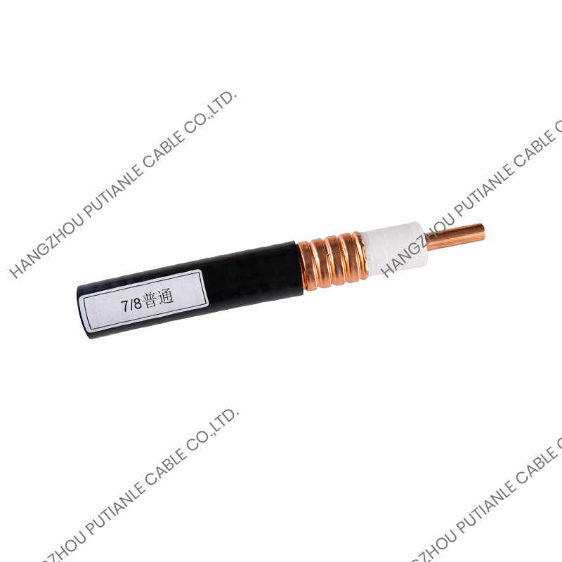
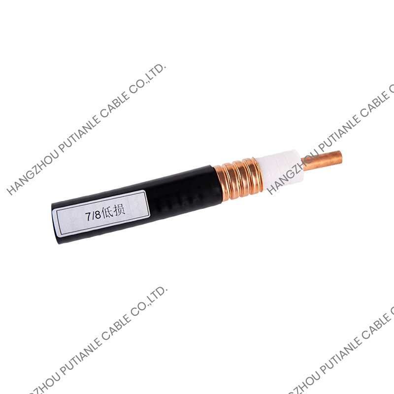
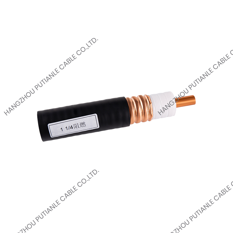
Construction varies widely. A single copper braid is flexible and easy to terminate. A double braid improves coverage and shielding effectiveness. A bonded foil plus braid combination gives excellent coverage at high frequencies but is harder to connectorize. At the high end sit corrugated copper and aluminum tubes, which behave like a rigid pipe: very low attenuation, high power handling and excellent mechanical stability for tower and trunk installations. Those tube designs also come in annular, spiral, low-loss and super-flexible variants, because bending radius is often the deciding factor on site.
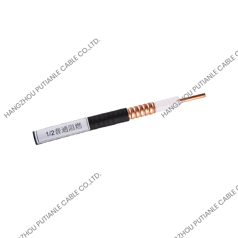 1/2" Annular Corrugated Copper Tube 50 Ohm Coaxial CableIntroducing the 1/2-inch Standard Corrugated Copper Tube 50 Ohm Coaxial Cable, a reliable conduit for RF signals in a variety of communication settings. This cable's s...View Product →
The Jacket: Protection You Only Notice When It Fails
The jacket is the layer nobody praises and everybody blames. Its material selection follows the installation environment: PVC for general indoor use, polyethylene for outdoor and direct burial where UV and moisture resistance dominate, and low-smoke zero-halogen compounds for tunnels, stations and other spaces where smoke density and toxicity are regulated. Flame-retardant grades such as those defined under IEC 60332 are specified when a cable must not propagate fire along a tray.
Thickness and adhesion also matter. A jacket that is too thin abrades during pulling; one that is too tightly bonded makes connector preparation slow and error-prone. We treat both as design parameters, not afterthoughts.
Connectors: The Component That Completes the Circuit
Strictly speaking, a connector is not part of the cable cross-section, yet ignoring it wastes everything the four layers were designed to achieve. An interface must match the cable impedance, hold a stable contact, and survive vibration and repeated mating. N-type, DIN and 4310 interfaces cover most of the RF work our customers do, and each is available in male and female forms with solder, crimp or clamp attachment depending on the cable family being terminated.
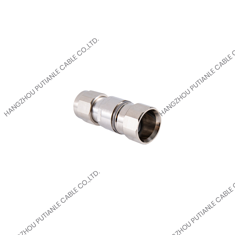 N Type Male Rf ConnectorIntroducing the N-Type Male RF Connector, a precision component designed for the reliable transmission of radio frequency signals. This connector is a staple in the fi...View Product →
How Component Choices Shape Real-World Performance
Once the individual parts are understood, the practical question becomes how they work together. In our experience, five effects drive most specification decisions:
- Attenuation, controlled mainly by conductor size, dielectric loss and shield construction.
- Power handling, which depends on conductor mass and the ability of the cable to dissipate heat.
- Flexibility, decided by stranded versus solid conductors and by braided versus corrugated outer conductors.
- Shielding effectiveness, driven by coverage percentage and the number of shielding layers.
- Service life, which usually comes down to jacket material and moisture protection.
What We Check Before a Coaxial Cable Leaves the Factory
Because the four layers interact, measuring them in isolation is not enough. We verify structural return loss across the operating band, capacitance and velocity of propagation, conductor elongation, jacket thickness and adhesion, and we run flame tests where the specification calls for them. Our manufacturing has been recognized as a national high-tech enterprise, and the factory holds ISO system certification, CE and RoHS environmental certification, Tel approval and network access certification for broadcast applications.
That discipline is also why our catalog has grown to more than 1,000 products across eight major families, covering 50-ohm and 75-ohm coaxial cable, fiber optic cable, leakage feeder, connectors and jumper assemblies. If you would like to see how these layers come together in finished products, you can explore our full cable range or send us a drawing of the application you have in mind.
Understanding the components of a coaxial cable is really about understanding how four simple layers share one axis and one responsibility each. Get the conductor and dielectric right and the cable behaves electrically. Get the shield right and it stays clean in a crowded spectrum. Get the jacket right and it still performs ten years after installation.
When a design or a field problem comes to us, we usually start by asking which of those four layers is actually under strain. Answering that question first tends to save a great deal of time, rework and cost further down the project.