
 中文简体
中文简体 English
 Español
Content
- 1 What Is a 75 Ohm Aluminum Tube Cable?
- 2 Construction and Physical Structure of the Cable
- 3 Why 75 Ohms Is the Standard for Video and Broadcast Applications
- 4 Key Performance Specifications to Evaluate
- 5 Common Cable Sizes and Their Typical Applications
- 6 Primary Industries and Applications
- 7 Installation Considerations and Best Practices
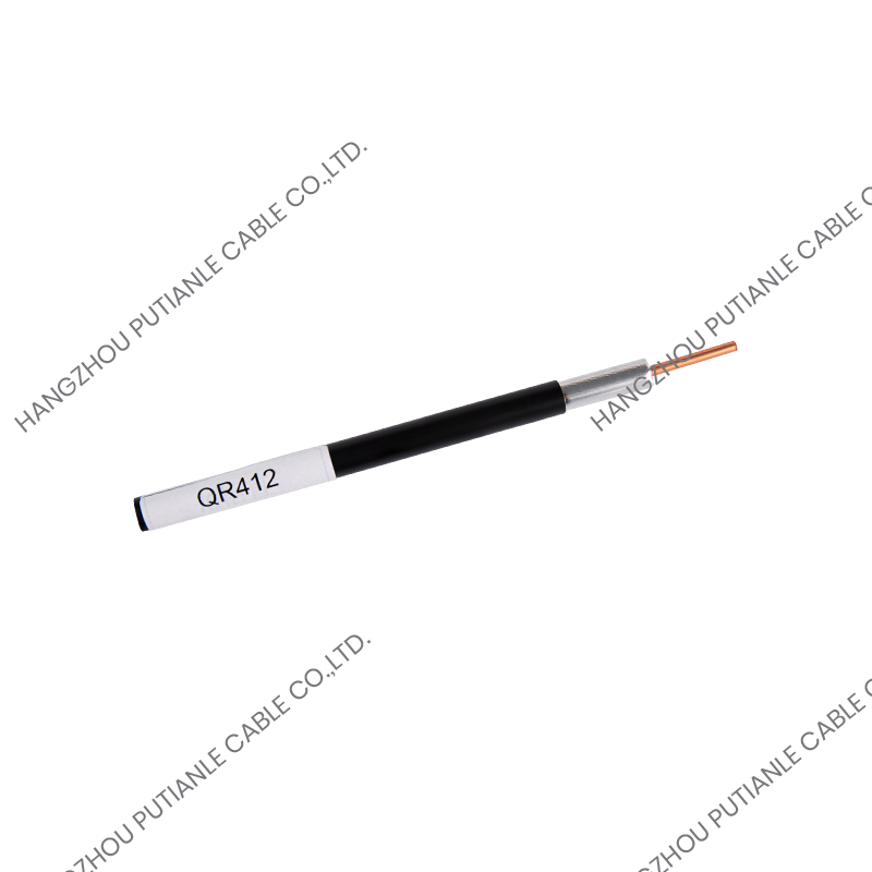
What Is a 75 Ohm Aluminum Tube Cable?
A 75 ohm aluminum tube cable is a type of coaxial cable engineered to maintain a characteristic impedance of 75 ohms throughout its length, using an aluminum tube as the outer conductor instead of the braided wire shield found in conventional flexible coaxial cables. This construction gives it a rigid or semi-rigid physical form and exceptional signal integrity over long transmission distances. The 75 ohm impedance value is the international standard for video signal transmission, broadcast infrastructure, cable television distribution networks, and satellite communication systems, making this cable type a cornerstone component in professional signal distribution wherever high-frequency signals must travel without significant loss or distortion.
The aluminum tube outer conductor serves a dual function: it provides the electromagnetic shielding necessary to prevent signal leakage and external interference, and it forms the structural backbone of the cable itself. Unlike flexible coaxial cables that rely on a braided or foil shield, the continuous aluminum tube creates a seamless, 360-degree conductive barrier with virtually no gaps. This results in shielding effectiveness that far exceeds what braided constructions can achieve, typically delivering attenuation of external interference in excess of 100 dB across a wide frequency range. The combination of precise impedance control and superior shielding makes 75 ohm aluminum tube cable the preferred choice for trunk lines and feeder cables in large-scale signal distribution systems.
Construction and Physical Structure of the Cable
Understanding the internal architecture of a 75 ohm aluminum tube cable is essential for selecting the right product and understanding its performance characteristics. The cable consists of several concentric layers, each contributing a specific function to the overall performance of the transmission line.
Inner Conductor
The center conductor is typically a solid copper or copper-clad aluminum (CCA) rod that carries the signal current. Copper provides the lowest resistivity of any practical conductor material, minimizing ohmic losses along the cable length. In larger cable sizes, copper-clad aluminum is sometimes used to reduce weight while maintaining adequate conductivity. The diameter of the inner conductor, in combination with the dielectric material and outer conductor dimensions, determines the characteristic impedance of the cable. For a 75 ohm impedance target, the ratio of the outer conductor inner diameter to the inner conductor outer diameter is precisely controlled during manufacturing to hit the required value within tight tolerances — typically ±1 ohm or better in quality-certified products.
Dielectric Spacer
Between the inner conductor and the aluminum tube outer conductor sits the dielectric material, which provides electrical insulation and physical support while also influencing the velocity of propagation and attenuation characteristics of the cable. The most common dielectric material used in aluminum tube cables is solid or foam polyethylene. Foam polyethylene — in which the polyethylene is expanded with gas bubbles to reduce its effective dielectric constant — lowers signal attenuation compared to solid polyethylene and is used in higher-performance cable versions where minimizing loss over long runs is a priority. Some premium cables use a disc-and-air or corrugated spacer design that replaces most of the solid dielectric with air, achieving the lowest possible dielectric losses at the expense of some mechanical complexity.
Aluminum Tube Outer Conductor
The outer conductor is the defining feature of this cable type. It is formed from aluminum strip that is longitudinally folded and welded or seam-formed around the dielectric core to create a continuous, seamless tube. In some cable designs, the aluminum tube is corrugated — formed into a helical or annular corrugated profile — which provides flexibility while retaining the structural and shielding advantages of a tube construction. Smooth-wall aluminum tube cables are more rigid and are typically used for fixed, direct-burial, or conduit-installed applications, while corrugated aluminum tube cables can be bent and routed around obstacles during installation, making them more versatile in complex installation environments.
Outer Jacket
The outermost layer is a protective jacket made from polyethylene (PE), low-smoke zero-halogen (LSZH) compound, or occasionally PVC, depending on the installation environment and applicable fire safety codes. Black UV-stabilized polyethylene is the standard jacket material for outdoor, direct-burial, and aerial installation applications because of its excellent resistance to sunlight, moisture, and soil contact. LSZH jackets are specified for installations in enclosed spaces such as building risers, plenum areas, tunnels, and transportation infrastructure where toxic smoke generation in the event of a fire must be minimized.
Why 75 Ohms Is the Standard for Video and Broadcast Applications
The choice of 75 ohms as the characteristic impedance for video transmission systems is not arbitrary — it represents an optimized compromise between two competing performance objectives in coaxial cable design. In a coaxial cable, minimum signal attenuation per unit length is achieved at approximately 77 ohms, while maximum power handling capability is achieved at approximately 30 ohms. The value of 75 ohms was chosen as the practical standard for video and broadcast applications because it is very close to the minimum attenuation point, meaning that 75 ohm systems deliver the lowest possible signal loss for a given cable size — a critical advantage in long-distance signal distribution where every decibel of signal level matters.
In contrast, the 50 ohm impedance standard used in RF test equipment, cellular antenna systems, and general-purpose radio frequency applications is a compromise that favors power handling and is matched to the impedance of common antenna configurations. Mixing 50 ohm and 75 ohm components in a signal chain introduces impedance mismatches that cause signal reflections, standing waves, and loss of signal quality — which is why it is essential to maintain consistent 75 ohm impedance throughout every component in a video or broadcast distribution system, from the cable itself through all connectors, splitters, amplifiers, and terminating loads.
Key Performance Specifications to Evaluate
When comparing different 75 ohm aluminum tube cable products, several technical parameters directly determine how well the cable will perform in a given application. Understanding these specifications enables informed purchasing decisions and accurate system design.
- Attenuation (dB/100m): The reduction in signal power per unit length of cable, measured in decibels per 100 meters at a specified frequency. Lower attenuation values indicate better signal retention over long cable runs. Attenuation increases with frequency, so specifications are typically provided at multiple frequencies — for example, at 100 MHz, 1 GHz, and 3 GHz — to allow assessment across the operating bandwidth of the system.
- Velocity of propagation (%): The speed at which signals travel through the cable expressed as a percentage of the speed of light in a vacuum. Higher velocity of propagation — typically between 82% and 93% for foam dielectric cables — means lower signal delay and phase distortion over long cable runs, which is important in time-sensitive broadcast and distribution systems.
- Return loss (dB): A measure of how well the cable maintains its target 75 ohm impedance along its length. Higher return loss values indicate better impedance uniformity and fewer signal reflections. A return loss of 23 dB or better is typically required for broadcast-grade applications.
- Shielding effectiveness (dB): The degree to which the aluminum tube outer conductor prevents signal leakage out of the cable and interference ingress from external sources. Aluminum tube constructions typically achieve shielding effectiveness values exceeding 100 dB, compared to 85 to 95 dB for high-quality braided cables.
- Minimum bend radius: The smallest radius to which the cable can be bent without damaging the dielectric or outer conductor. Smooth-wall aluminum tube cables have larger minimum bend radii than corrugated versions and must be handled accordingly during installation planning and execution.
- Operating temperature range: The range of ambient temperatures within which the cable can be installed and operated without degradation of electrical or mechanical performance. Most outdoor-rated aluminum tube cables are specified for operation from -40°C to +85°C.
Common Cable Sizes and Their Typical Applications
75 ohm aluminum tube cables are manufactured in a range of standard sizes, with larger diameters offering lower attenuation at the cost of reduced flexibility and increased installation complexity. The table below shows the most common cable sizes and their primary application areas:
| Cable Size | Outer Diameter (approx.) | Attenuation at 1 GHz | Typical Application |
| 1/4 inch | ~10 mm | ~14 dB/100m | Short building drops, indoor distribution |
| 3/8 inch | ~16 mm | ~9 dB/100m | Medium-length feeder runs, CATV distribution |
| 1/2 inch | ~22 mm | ~6 dB/100m | Trunk lines, broadcast facility backbone |
| 7/8 inch | ~38 mm | ~3.5 dB/100m | Long-distance trunk, headend interconnects |
| 1-5/8 inch | ~54 mm | ~2 dB/100m | High-power broadcast transmitter feedlines |
Primary Industries and Applications
The performance characteristics of 75 ohm aluminum tube cable make it the dominant transmission line technology in several industries where signal quality, long-distance distribution, and system reliability are paramount.
Cable Television and Broadband Distribution
Cable television network operators use 75 ohm aluminum tube cable — commonly known in this context as hardline coaxial cable or trunk cable — as the backbone of their hybrid fiber-coaxial (HFC) distribution networks. After the optical fiber from the headend is converted to RF signal at a fiber node, aluminum tube cable carries the combined television, internet, and telephony signals through the neighborhood distribution network to individual homes and businesses. The low attenuation of large-diameter aluminum tube cable allows amplifier spacing of 500 meters or more, minimizing the number of active amplifiers required in the network and improving overall system reliability. DOCSIS 3.1 and emerging DOCSIS 4.0 networks, which extend signal bandwidth to 1.2 GHz and 3 GHz respectively, increasingly demand the higher-performance aluminum tube cables capable of low-loss transmission at these elevated frequencies.
Broadcast and Television Production Facilities
Television broadcast facilities, sports stadiums, news production centers, and outside broadcast vehicles use 75 ohm aluminum tube cable for interconnecting signal routing equipment, distributing video signals across large facilities, and connecting antenna systems to transmission equipment. The superior shielding performance of aluminum tube cable is especially valuable in broadcast environments where high-power transmitters, studio lighting dimmers, and dense concentrations of electronic equipment create challenging electromagnetic interference conditions that would compromise signal quality in less well-shielded cable types.
Satellite Ground Stations and Telecommunications
Satellite earth stations and telecommunications facilities use 75 ohm aluminum tube cable to connect dish antennas to indoor signal processing equipment over distances that can range from tens to hundreds of meters. The low-loss characteristics of large-diameter aluminum tube cable are critical in these applications because the received signal power from a satellite is extremely small, and any additional attenuation in the cable run directly degrades the system noise figure and reduces the link margin available for maintaining reliable communication during rain fade and other atmospheric impairments.
Installation Considerations and Best Practices
Proper installation of 75 ohm aluminum tube cable requires attention to several factors that differ significantly from the installation of flexible coaxial cables. The rigid or semi-rigid nature of aluminum tube cable, combined with its larger size and weight, demands careful planning and the use of appropriate tools and hardware.
Bending must always be performed within the minimum bend radius specified by the cable manufacturer. Exceeding the minimum bend radius deforms the aluminum tube outer conductor, which changes the local impedance of the cable at the bend point and introduces signal reflections that degrade system performance. For smooth-wall aluminum tube cables, factory-made bends are preferred over field bending wherever possible. Corrugated aluminum tube cables can be bent in the field using a cable bending tool that maintains the minimum bend radius throughout the operation.
Connectors used with aluminum tube cable must be specifically designed and rated for the cable size and type being installed. Improper connector installation is one of the most common sources of impedance discontinuities, signal leakage, and moisture ingress in field-installed coaxial systems. Connectors should be installed using the manufacturer's specified torque values and installation tools, and all outdoor connector interfaces should be sealed with self-amalgamating tape or weatherproofing compound to prevent moisture penetration, which can cause corrosion of the aluminum outer conductor and dramatic increases in signal attenuation over time. Cable support hardware — hangers, clamps, and brackets — should be sized for the specific cable diameter and spaced at intervals that prevent excessive sag or mechanical stress on the cable and its connectors during thermal expansion and contraction cycles across the operating temperature range.


